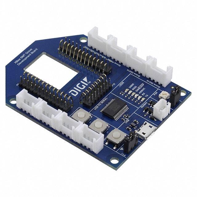
XBee Grove Development Board
The XBee Grove Development Board is a simple-to-use base unit. You can use it to evaluate
XBee modules, as it connects any XBee/XBee-PRO module to a PC or microcontroller. One of
the main features of the board is that it has several Grove connectors where you can plug in a
Grove Module. You can learn more about the Grove module on the Seeed Studio wiki.
There are two variants of the board: THT and SMT.
This guide includes the following topics:
•
Overview
XBee THT Grove Development Board
�XBee SMT Grove Development Board
��Overview
On this page:
•
•
•
•
•
Mechanical
Power supply
XBee connector
USB
Reset button
�•
•
•
•
•
•
•
•
•
Commissioning button
Association LED
RSSI LED
User LED and User button
On/Sleep LED
Potentiometer
I2C
Grove connectors
Loopback jumper
Mechanical
The XBee Grove Development Board is 44.8mm x 66mm with a shape similar to a regular XBee
module.
The board provides four 3.2 mm assemble drills.
�Power supply
�The XBee Grove Development Board can be powered from the 5V supply available on the USB
connector or from an external battery connected to a 2-pin, 2mm pitch, PH type connector from
JST. When both supplies are available, the board is powered from the USB.
The board has a 3.3V regulator that generates 500mA supply.
The following table shows the pinout of the battery connector:
Battery connector Signal
Comments
1
VBAT Battery supply input
2
GND
XBee connector
The XBee Grove Development Board provides two 10-pin, THT, 2mm pitch sockets to connect a
THT XBee module. It is compatible with both regular XBee/XBee-PRO and
programmable XBee.
�Footprints for two 10-pin, THT, 2.54mm pitch connectors are available on the board. These
footprints can be used to solder a pin header on the top or bottom to access the XBee signals or
to connect the XBee Grove Development Board to a bread board.
The following table shows the pinout of the XBee connector:
LEFT
Pin
Signal
RIGHT
Comments
Pin
Signal
1
3.3V
XBee supply
1
2
3
4
5
XBEE_TX
XBEE_RX
DIO12
RESET_N
2
3
4
5
6
RSSI/PWM0
To serial to USB device
To serial to USB device
To GROVE_DIO12
To reset button
To RSSI LED and
GROVE_PWM
Comments
To GROVE_DIO4 and user
DIO4
LED/button
XBEE_CTS_N To serial to USB device
DIO9
To On/Sleep LED
VREF
ASSOC_LED To association LED
6
XBEE_RTS_N To serial to USB device
�7
8
9
DIO11/I2C_SDA To GROVE_I2C
7
Connected to
XBEE_PIN8
8
breadboard header
XBEE_DTR_N To serial to USB device 9
10 GND
AD3
To potentiometer
AD2
To GROVE_AD2
DIO1/ISC_SCL To GROVE_I2C
To commissioning button
10 AD0/CB
and GROVE_AD0
USB
The XBee Grove Development Board includes a microUSB connector and an FT232RL USB to
RS232 converter to communicate with the serial port of the XBee.
A green LED and a yellow LED show the status of the TX and RX lines.
The hardware flow control signals of the XBee (XBee_RTS and XBee_CTS) are connected to
the FT232RL device. Two serial 0R resistors disconnect the flow control of the chip if this
functionality is not needed.
The XBEE_DTR_N signal is also connected to the FT232 chip. XCTU uses this signal to enter
in the boot loader and will recover the module from incorrect firmware. A configurable 0R
resistor disconnects this signal if the functionality is not needed.
A three-pin jumper configures the serial port in a loop back mode, connecting the RX and TX
lines together. When positions 1-2 are closed, the serial port is configured in normal mode. In
this mode, the serial port of the XBee is connected to the microUSB connector. If positions 2-3
are closed, the serial port will work in loopback mode. In this mode, the data transmitted by the
XBee will be connected to the RX pin.
�The USB connector is also used to power the board through the VBUS line.
Reset button
�The XBee Grove Development Board has a reset button to reboot the XBee module.
Commissioning button
The XBee Grove Development Board has a push button connected to the commissioning pin of
the XBee module. The commissioning pin of the XBee is also connected to the Grove AD0
connector. You can use the commissioning push button in ZigBee or DigiMesh to aid in
deploying devices in a network.
�Association LED
�The XBee Grove Development Board provides an LED connected to the association pin of the
XBee module.
For more information about association, read the XBee Product Manual.
RSSI LED
The XBee Grove Development Board provides an LED connected to the RSSI/PWM0 pin of the
XBee module. The RSSI/PWM signal is also connected to the PWM Grove connector.
If the PWM0 pin (P0) is configured as RSSI, the brightness of this LED will display the signal
strength of the last packet received.
�User LED and User button
The XBee Grove Development Board provides a user LED and a user button. Both share the
same XBee I/O pin, DIO4.
Although the user LED and user button share the same pin, you can use only one at a time.
�On/Sleep LED
The XBee Grove Development Board provides an LED connected to the On/Sleep pin
(DIO9). This LED in on when the XBee module is awake, and off when it is asleep.
�Potentiometer
The XBee Grove Development Board provides a 10K potentiometer to generate analog signal
between 3.3V and 0V. The output of the potentiometer is connected to the AD3 pin (D3) of the
XBee.
�One jumper is used to disconnect the 3.3V supply from the potentiometer to save power when it's
not used.
I2C
�The XBee Grove Development Board provides an I2C bus. This I2C bus can be used with XBee
programmable modules.
Regular XBee/XBee-PRO modules don't provide an I2C bus, but you can connect a digital
Grove sensor.
�The following table shows the pinout of the Grove I2C connector:
Grove I2C
Signal
Comments
1
DIO1/I2C_SCL
2
DIO11/I2C_SDA
3
3.3V
4
GND
Grove connectors
The XBee Grove Development Board provides six Grove connectors connected to the XBee
pins. Two connectors are connected to digital I/O pins, two connectors are connected to two
digital/analog I/O pins, one connector is connected to the RSSI/PWM0 pin, and another is
connected to the I2C bus of the microcontroller placed in the socket (programmable XBee.)
You can find a large list of Grove sensors and actuators that can be plugged in to these
connectors here.
�The following tables show the pinout of the Grove connectors:
Grove DIO12 Signal Comments
1
DIO12
2
3
3.3V
4
GND
Grove DIO4 Signal
Comments
1
DIO4 Signal connected to user LED/button
2
3
3.3V
4
GND
Grove AD0 Signal
Comments
1
AD0/CB Signal connected to commissioning button
2
3
3.3V
4
GND
Grove I2C
Signal
Comments
1
DIO1/I2C_SCL
2
DIO11/I2C_SDA
3
3.3V
4
GND
Grove PWM0
Signal
Comments
1
RSSI/PWM0 Signal connected to RSSI LED
2
3
3.3V
4
GND
Grove AD2 Signal Comments
1
AD2
2
3
3.3V
4
GND
Loopback jumper
�The XBee Grove Development Board provides a three-pin jumper to connect the UART to the
USB (normal mode) or to make a loopback connection between the RX and TX signals of the
UART.
In loopback mode, the RX line is connected to the TX line, which causes any received data to be
transmitted back. This is used in transparent mode to check the signal strength and perform a
range test.
�
很抱歉,暂时无法提供与“76000979”相匹配的价格&库存,您可以联系我们找货
免费人工找货- 国内价格 香港价格
- 1+309.936551+40.08323