(877) 634-0982
www.digipwr.com
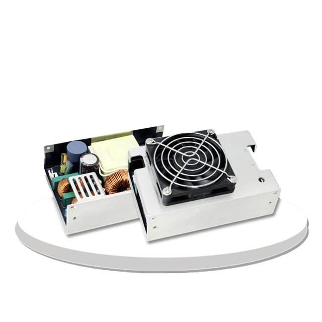
HD500 SERIES
AC-DC ITE SWITCHING PSU - 500 WATT
KEY FEATURES
Digital Power’s HD500 Series are switching power supplies that produce
superior output wattages with natural convection. The series include enclosed,
open fame and U bracket format with output voltage options of 12V, 24V and
48V. Featured with compact, low profile footprint, and best-in-class
performance, HD500 Series are optimal for broad Industrial and
Telecommunication Applications.
Designed with energy saving in mind, Digital Power’s HD500 Series boasts not
only high operating efficiency up to 93%. but also high-power density with full
input range of 90-264Vac and built-in active PFC.
HD500 operates over wide temperature range from -30°C to +80°C with
complete protections and certified to UL / IEC / EN 62368-1.
1
�(877) 634-0982
www.digipwr.com
PRODUCT
SPECIFICATION
Enclosed, U Bracket
Switching Power
Supply
•
Universal Input 90-264Vac
•
High Efficiency up to 93%
•
Safety Approval to UL / IEC / EN
62368-1
•
-30°C to +80°C Wide Operation
Temperature Range
•
Operating Altitude 5000M
•
Active PFC Function
•
I/O Isolation 4000VAC
•
Built-in 12V/0.3A Auxiliary Output
(HD500U)
•
Standby 5V@1A with Fan
•
Standby 0.4A without Fan (HD500U)
•
Ultra Compact Size:
HD500E:5.11 x 3.25 x 2.42 Inches
HD500U:5.11 x 3.25 x 1.6 Inches
HD500 Series
2
�(877) 634-0982
www.digipwr.com
ELECTRICAL SPECIFICATION - HD500U SERIES
Model No.
Max Output Wattage (with 30CFM FAN) (W)
Max Output Wattage (Conduction Cooling) (W) (Note 6)
Max Output Wattage (Natural Convection) (W)
Voltage(Note 3)
Frequency (Hz)
Current (Full load)
Input
Inrush Current (3% Load, 12V (Aux) / 0.3A., 12V (Aux) need 0.1A Minimum Load, Auxiliary voltage
output ground 10.2~13.3V
5. Strongly recommend to conduct this test with DC Voltage. If customer wishes to test with AC
Voltage, please disconnect all Y-Capacitors from Digital Power power supply.
6. The size of the suggested aluminum plate is shown as below. And for optimizing thermal
performance, the aluminum plate must have an even and smooth surface (or coated with thermal
grease), and HD500 series must be firmly mounted at the center of the aluminum plate.
HD500 Series
450 x 450 x 3.0 mm
7.
CAUTION: Double pole, neutral fusing. Disconnect mains before servicing.
HD500 Series
4
�(877) 634-0982
www.digipwr.com
ELECTRICAL SPECIFICATION - HD500U SERIES
DERATING
If input voltage is lower than
100VAC, please refer to the
output derating V.S. input voltage
curve for details
HD500 Series
5
�(877) 634-0982
www.digipwr.com
MECHANICAL DIMENSIONS– HD500U SERIES
A= For fixture to chassis only
A=M3x0.5P
B=For fixture to pcb/chassis
only
B=M3x0.5P
Torque:3+/-0.5 Kgf.cm
Brands
Alex
PIN#
Single
1
AC IN (N)
2
NO PIN
Mating
Housing
9396-3
JST
Terminal
Mating
Housing
Terminal
96T series
VHR-3N
SVH-41T-P1.1
3
AC IN (L)
4
+DC OUT Terminal : M5 Pan HD screw in 2 positions.
-DC OUT Torque to 8 lbs-in(90cNm) max
5
6
PE
─
─
─
─
Connector Pin (CN1)
Cherng Weei
Brands
PIN#
Single
C1
-5V SB
C2
+5V SB
C3
GND
C4
DC-OK
C5
-RC
C6
+RC
C7
C8
Mating
Housing
Terminal
JST
Mating
Housing
ASSEMBLY INSTRUCTIONS
U Case T=1.5mm
Customer is advised to screw into the
threads no more than 1.5mm
Chassis of
HD500U
Series
Terminal
T=1.5mm
Connector Pin (FAN)
PHD-H20PHD-T20
2X4P
PHDR08VS
SPHD001T- P0.5
Brands
PIN#
Single
-S
F1
+12V
+S
F2
GND
Alex
JST
Mating
Mating
Terminal
Terminal
Housing
Housing
8821-2
8820T
XHP-2
SXH002TP0.6
HD500 Series
6
�(877) 634-0982
www.digipwr.com
MECHANICAL DIMENSIONS– HD500U SERIES
FUNCTION DESCRIPITON of CN1
Pin No.
C1
Function
-5VSB
C2
+5VSB
C3
C4
C5
GND
DC OK
-RC
C6
+RC
C7
-S
C8
+S
Description
This pin connects to the negative terminal(-V). Return for DC-OK and -RC signal output.
Stand by voltage output ground 4.2~5.5V,
referenced to pin C1(-5VSB). The maximum load
current is 1A with Fan, 0.4A without Fan..
This pin connects to the negative terminal(-V). Return for DC-OK and -RC signal output.
DC-OK Signal is a DC output, referenced to pin C3(DC-OK GND).
This pin connects to the negative terminal(-V). Return for DC-OK and -RC signal output.
Turns the output on and off by electrical or dry contact between pin C5 (-RC), Short: Power
OFF, Open: Power ON. The input voltage must be less than 1V in order to disable VOUT and
greater than 3.3V (up to 5V) to enable it.
Negative sensing. The -S signal should be connected to the negative terminal of the load. The -S
and +S leads should be twisted in pair to minimize noise pick-up effect.
Positive sensing. The +S signal should be connected to the positive terminal of the load. The +S and
-S leads should be twisted in pair to minimize noise pick-up effect.
FUNCTION MANUAL & APPLICATION NOTE
1.
DC-OK Signal
Between
DC-OK and GND
Output
Status
3.7~6V
0~1V
ON
OFF
2. Remote Control
It can be turned ON/OFF by using the "Remote Control" function.
Between
+RC and -RC
SW ON (Short)
SW OFF (Open)
Output
Status
OFF
ON
3. +S and -S Sense
Shorter wiring to each unit is recommended, as well as twisting +S and -S in pairs, as shown below
HD500 Series
7
�(877) 634-0982
www.digipwr.com
ELECTRICAL SPECIFICATION - HD500E SERIES
Model No.
Max Output Wattage (W)
Voltage (Note 3)
Frequency (Hz)
Current (Full load)
Input
Inrush Current (3% Load, 12V (Aux) / 0.3A., 12V (Aux) need 0.1A Minimum Load, Auxiliary voltage
output ground 10.2~13.3V
5. Strongly recommend to conduct this test with DC Voltage. If customer wishes to test with AC
Voltage, please disconnect all Y-Capacitors from Digital Power power supply.
6. CAUTION: Double pole, neutral fusing. Disconnect mains before servicing.
DERATING
If input voltage is lower than 100VAC, please refer to the output derating V.S. input voltage
curve for details
HD500 Series
9
�(877) 634-0982
www.digipwr.com
MECHANICAL DIMENSIONS – HD500E SERIES
A= For fixture to chassis only
A=M3x0.5P
B=For fixture to pcb/chassis
only
B=M3x0.5P
Torque:3+/-0.5 Kgf.cm
Brands
PIN#
Single
1
AC IN (N)
2
NO PIN
Alex
Mating
Terminal
Housing
Mating
Housing
Terminal
9396-3
VHR-3N
SVH-41TP1.1
96T series
JST
3
AC IN (L)
4
+DC OUT Terminal : M5 Pan HD screw in 2 positions.
-DC OUT Torque to 8 lbs-in(90cNm) max
5
Connector Pin (CN1)
Cherng Weei
Brands
Mating
Housing
Terminal
Chassis of
HD500E
Series
JST
Mating
Housing
ASSEMBLY INSTRUCTIONS
U Case T=1.5mm
Customer is advised to screw into the
threads no more than 1.5mm
PIN#
Single
Terminal
C1
-5V SB
C2
+5V SB
C3
GND
C4
DC-OK
C5
-RC
C6
+RC
PIN#
Single
C7
-S
F1
+12V
C8
+S
F2
GND
T=1.5mm
Connector Pin (FAN)
PHD-H202X4P
PHD-T20
PHDR08VS
SPHD-001TP0.5
Brands
Alex
JST
Mating
Mating
Terminal
Terminal
Housing
Housing
8821-2
8820T
XHP-2
SXH002TP0.6
10
HD500 Series
�MECHANICAL DIMENSIONS – HD500E SERIES
FUNCTION DESCRIPITON of CN1
Pin No.
C1
Function
-5VSB
C2
+5VSB
C3
C4
C5
GND
DC OK
-RC
C6
+RC
C7
-S
C8
+S
Description
This pin connects to the negative terminal(-V). Return for DC-OK and -RC signal output.
Stand by voltage output ground 4.2~5.5V,
referenced to pin C1(-5VSB). The maximum load
current is 1A with Fan, 0.4A without Fan..
This pin connects to the negative terminal(-V). Return for DC-OK and -RC signal output.
DC-OK Signal is a DC output, referenced to pin C3(DC-OK GND).
This pin connects to the negative terminal(-V). Return for DC-OK and -RC signal output.
Turns the output on and off by electrical or dry contact between pin C5 (-RC), Short: Power
OFF, Open: Power ON. The input voltage must be less than 1V in order to disable VOUT and
greater than 3.3V (up to 5V) to enable it.
Negative sensing. The -S signal should be connected to the negative terminal of the load. The -S
and +S leads should be twisted in pair to minimize noise pick-up effect.
Positive sensing. The +S signal should be connected to the positive terminal of the load. The +S and
-S leads should be twisted in pair to minimize noise pick-up effect.
FUNCTION MANUAL & APPLICATION NOTE
1.
DC-OK Signal
Between
DC-OK and GND
Output
Status
3.7~6V
0~1V
ON
OFF
2. Remote Control
It can be turned ON/OFF by using the "Remote Control" function.
Between
+RC and -RC
SW ON (Short)
SW OFF (Open)
Output
Status
OFF
ON
3. +S and -S Sense
Shorter wiring to each unit is recommended, as well as twisting +S and -S in pairs, as
shown below
Digital Power Corporation
1635 S Main Street.
Milpitas, CA 95035 USA
T: (877) 634-0982 sales@digipwr.com
F: (510) 657-6634
www.digipwr.com
Digital Power Corporation designs and manufactures full custom,
value added and standard comprehensive power solutions for the
most demanding applications in the defense, healthcare, telecom,
and industrial markets.
11
HD500 Series
�
很抱歉,暂时无法提供与“HD500”相匹配的价格&库存,您可以联系我们找货
免费人工找货