Product Specification
FDB-1032-SFP+ Evaluation Board for SFP/SFP+/SFP28
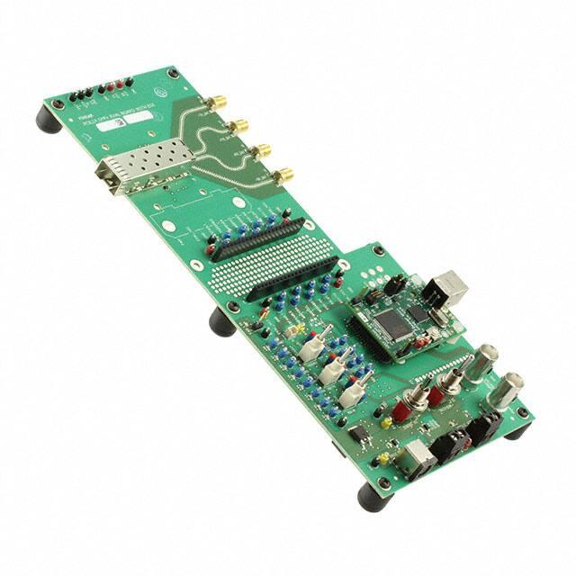
OVERVIEW
Finisar’s FDB-1032-SFP+ Evaluation Board
is designed for testing and evaluating all
SFP, SFP+ and SFP28 transceivers as well
as SFPwire® Active Optical Cables. This is
not a module compliance board, but it is
compatible with MSA compliant SFP, SFP+
and SFP28 transceivers.
CONTENTS
The board consists of a single SFP28 edge
connector and SFP28 cage assembly, four
50-ohm SMA female coaxial connectors
(J15-J18) for the high-speed differential
transmitter input and receiver output
signals, and test points for monitoring the
following pins:
Module RX_LOS
Module RX Rate Select 0
Module TX Rate Select 1
Module Absent
TWI (Two Wire Interface) SCL and SDA
TX Disable
TX Fault
Eval Board Ground and Vcc
Module Vcc RX and TX
Module Ground
Case Ground
The Evaluation Board has LED’s for the:
RX_LOS
RX Rate Select 0
TX Rate Select 1
Module Absent
TWI – SDA and SCL (Low)
TX Disable
TX Fault
Eval Board Power 5V
Eval Board Power 3.3V
© Finisar Corporation 03FEB2016 Rev C
Customized Finisar Software that is specific
to this product is available. Please contact
your local Finisar Representative for details.
The GUI needs to be installed on a
Windows® XP or 7 Operating System (32bit
or 64bit machine) that has an available
USB port. The USB (type B) port is on the
daughter card (called a FDB-INT-USB3).
Page 1
�SPECIFICATIONS
The FDB-1032-SFP+ Evaluation Board has
several different power options:
• A laboratory grade power supply with
a voltage of 3.3VDC at a maximum
of 1.2A at “Eval_Vcc” (J12); Set S7
to “5V REG”. Set S8 to
“COMBINED”. This will use the one
power supply to power the Eval
board and the SFP. Note that there
will be a voltage drop at the SFP due
to a diode that protects against
accidental reverse voltages. It is
recommended to measure the Vcc to
the SFP at the “Mod_Vcc” tap near
the SFP cage to make sure it is
within operating limits. This power
drop can be avoided in this setting
by attaching the power supply to
Mod_Vcc (J14), but the voltage
protection will also be avoided.
• An 8-20VDC source (e.g. laptop
power supply) at J7; Set S7 to “5V
REG”. Set S8 to “COMBINED”.
This is the recommended
configuration. The Eval Board has
reverse voltage protection and is
fused against shorts, but there is no
voltage drop at the SFP connector.
The jumper-hook labeled 8-20VDC
and the ground pin next to it, may
also be used in this configuration.
• A laboratory grade power supply with
a voltage of 3.3VDC at a maximum
of 1.2A at “Module_Vcc” (J14); Set
S7 to “5V USB”. Set S8 to
“SEPARATE”. This will use the
power supply to power the SFP
alone and have the Eval board
powered by the USB. There is no
reverse voltage protection diode on
this supply input.
• For Class 1 (1W max) SFP/SFP+/
SFP28 power applications, power via
USB. Set S7 to “5V USB”. Set S8 to
“COMBINED”. This will use the USB
voltage for the Eval board as well as
the SFP. It is recommended to
measure the Vcc to the SFP at
© Finisar Corporation 03FEB2016 Rev C
“Mod_Vcc” near the SFP cage to
make sure it is within operating
limits.
Note that the MSA compliant pi filter will still
be used for the SFP port in any of the
above configurations.
The high speed lines are designed so there
is
很抱歉,暂时无法提供与“FDB-1032-SFP+”相匹配的价格&库存,您可以联系我们找货
免费人工找货