Multiple-Joint Hinges
GN 7237
Stainless Steel, Internal Mounting, with Opening Angle 180°
Metric
3 Type
L Fixing angle piece left
R Fixing angle piece right
Metric table
Dimensions in: millimeters - inches
2
l1
d
40 5.3
1.57 .21
h1
h2
h3
7.5 28 2.5
.30 1.10 .10
l2
l3
l4
l5
26 36 70.1 105.2
1.02 1.42 2.76 4.14
50 6.5
1.97 .26
10 35 2.5
.39 1.38 .10
60 8.5
2.36 .33
12.5 40 2.5
.49 1.57 .10
Specification
l8
l9
m1
m2
101.9 16 25 5
4.01 .63 .98 .20
r
s
78.5 4
3.09 .16
x
13
.51
y
29.5
1.16
35 46 92.3 140 102.8 39.3
1.38 1.81 3.63 5.51 4.05 1.55
134.7 27.8 30
5.30 1.09 1.18
105
4.13
5
.20
18
.71
38
1.50
40 61 116.5 179.5
1.57 2.40 4.59 7.07
172.2 37.2 36 8
6.78 1.46 1.42 .31
137.5 5
5.41 .20
19
.75
47
1.85
1
• Body
Stainless steel
NI
European Standard No. 1.4301 (AISI 304)
Matte tumbled finish
• Friction bearing
Bronze, self-lubricated
• RoHS compliant
On request
4
MT
l6
l7
74.5 27.4
2.93 1.08
125.2 51.3
4.93 2.02
6
.24
Information
GN 7237 stainless steel multiple-joint hinges are installed on the inside of flaps, hatches and doors to
save space and ensure protection against vandalism. The hinges have a maximum opening angle of
180°, which provides optimal accessibility and avoids the blocking of escape routes by open doors,
for example.
Use of this hinge type leaves housing exteriors free of attachments that do not match the design or that
should be avoided entirely in the interests of fast and easy cleaning.
Stainless steel multiple-joint hinges are generally used in pairs, meaning that one Type L and one type
R are used per opening. For higher loads, e.g. from large hatches, these can be supplemented with
additional hinges of either type.
• Other opening angles
see also...
• Construction Instructions and Load Capacity
• Other fixing angle pieces
• Spacer Plates GN 2370 (Stainless Steel)
• Other materials
• Stainless Steel Spacer Plates GN 2372 (Stainless Steel, with Tapped Insert)
• Other finishes
• Stainless Steel Spacer Plates GN 2376 (with Threaded Studs)
• Other max. wall thicknesses
• Other lifting motion
• With pneumatic spring connection
How to order
1
2
3
4
GN 7237-NI-40-L-MT
10
| 3.3 Hinging, Latching, Locking of Doors and Covers
1
Material
2
Length l1
3
Type
4
Finish
www.jwwinco.com | phone: 1-800-877-8351
�GN 7237 Multiple-Joint Hinges continued
Installation position – pivot characteristics
The stainless steel multiple-joint hinges can be installed to the housing either with slotted holes on the fixing angle piece that are either perpendicular or
parallel to the hinge axis. This results in the two pivot characteristics depicted.
Application examples
Adjustment and fastening options
The stainless steel multiple-joint hinges can be adjusted in three planes during
installation. For example, this allows adjustment for tolerances or establishing
of required compressive forces for seals.
Two planes can be adjusted via parallel or perpendicular slotted holes in the
fixing angle pieces. In the third plane, position corrections can be made using
the GN 2370 stainless steel spacer plates.
GN 2372 stainless steel spacer plates with tapped holes as well as GN
2376 stainless steel spacer plates with threaded studs are also available for
fastening the hinges. The latter can be welded on or inserted through the wall
from the outside and fastened in place. All accessory items are designed for
use with both fixing angle pieces.
www.jwwinco.com | phone: 1-800-877-8351
3.3 Hinging, Latching, Locking of Doors and Covers |
11
�GN 7237 Multiple-Joint Hinges continued
Design variants
Flaps, hatches and doors can be inset, surface-mounted or mitered. The maximum wall thicknesses and bend sizes for planned sheet metal constructions
arise from the respective installation type.
1. Fixing angle pieces mounted to the housing with slotted holes perpendicular to the hinge axis:
l1
s1 max.
b1
s 2 max.
b 2 max.
s 3 max.
b 3 max.
40
1.57
13
.51
1 ...
∞
24
.94
10
.39
10
.39
10
.39
50
1.97
19
.75
1 ...
∞
34
1.34
17
.67
16
.63
16
.63
60
2.36
25
.98
1 ...
∞
44
1.73
24
.94
21
.83
21
.83
2. Fixing angle pieces mounted to the housing with slotted holes parallel to the hinge axis:
l1
s 4 max.
b 4 max.
s5
b 5 max.
s 6 max.
b 6 max.
40
1.57
9
.35
27
1.06
1 ...
∞
13
.51
10
.39
10
.39
50
1.97
17
.67
35
1.38
1 ...
∞
19
.75
16
.63
16
.63
60
2.36
23
.91
45
1.77
1 ...
∞
25
.98
21
.83
21
.83
The design variants shown represent standard installation conditions. If the installation position of the hinge is changed or one of the two wall thickness
dimensions s or b are lower, the maximum achievable dimensions change independently of each other. This makes it possible in some cases to work with
larger wall thickness dimensions than those specified with the same hinge size. A simple design check via CAD or a test setup is therefore recommended.
12
| 3.3 Hinging, Latching, Locking of Doors and Covers
www.jwwinco.com | phone: 1-800-877-8351
�GN 7237 Multiple-Joint Hinges continued
Construction assembly
Load capacity
The maximum load of the stainless steel multiple-joint hinges specified below applies to the standard use cases and serves for orientation in the case
of deviating applications. The resulting forces lead to slight elastic deformation, which can be compensated for by means of the adjustment options, if
necessary.
Load capacity per hinge pair
l1
40 N
8.99 lbf
FA (axial)
F R (radial)
125 N
28.10 lbf
450 N
101.16 lbf
50 N
11.24 lbf
125 N
28.10 lbf
600 N
134.89 lbf
60 N
13.49 lbf
125 N
28.10 lbf
450 N
101.16 lbf
www.jwwinco.com | phone: 1-800-877-8351
3.3 Hinging, Latching, Locking of Doors and Covers |
13
�
很抱歉,暂时无法提供与“7237-NI-40-L-MT”相匹配的价格&库存,您可以联系我们找货
免费人工找货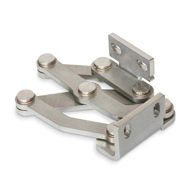


 工商网监
湘ICP备2023018690号
工商网监
湘ICP备2023018690号
