A
Datasheet
mFlexPIFA
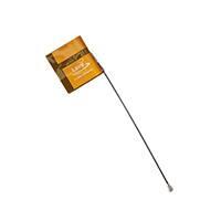
2.4 – 2.5 GHz mFlexPIFA +2 dBi Antenna, 100 mm cable length with U.FL or MHF4 connector
Version 2.1
�mFlexPIFA
Datasheet
REVISION HISTORY
Version
Date
Notes
2.0
15 Aug 2017
Initial Release on website
Sue White
2.1
20 Mar 2018
Added new antenna connector information;
transitioned to new template; updated contact
information
Jay White
Embedded Wireless Solutions Support Center:
http://ews-support.lairdtech.com
www.lairdtech.com/wireless
330-0243-R2.1
Contributors
2
Approver
Americas: +1-800-492-2320
© Copyright 2018 Laird. All Rights Reserved
Europe: +44-1628-858-940
The information in this document is subject to change without notice.
Hong Kong: +852 2923 0610
�mFlexPIFA
Datasheet
CONTENTS
1
Ordering Information ..................................................................................................................................................... 4
2
Key Features .................................................................................................................................................................. 4
3
Specifications ................................................................................................................................................................. 4
4
Physical Dimensions ....................................................................................................................................................... 5
5
Test Setup ...................................................................................................................................................................... 6
6
Flat Surface Antenna Measurements ............................................................................................................................. 7
Return Loss ........................................................................................................................................................................ 7
7
Flat Surface Antenna Radiation Performance ................................................................................................................. 8
7.1
Antenna Setup ...................................................................................................................................................... 8
7.2
Results – Flat Surface ............................................................................................................................................ 9
2400 MHz ...................................................................................................................................................................... 9
2440 MHz .................................................................................................................................................................... 11
2480 MHz .................................................................................................................................................................... 13
8
Curved Surface Antenna Radiation Performance.......................................................................................................... 15
8.1
Antenna Setup .................................................................................................................................................... 15
8.2
Results – Curved Surface ..................................................................................................................................... 16
2440 MHz .................................................................................................................................................................... 16
9
Optimal Installation Guide ........................................................................................................................................... 18
9.1
Flex Limits of the mFlexPIFA ................................................................................................................................ 20
10
Product Revision History .............................................................................................................................................. 21
11
Contacting Laird ........................................................................................................................................................... 21
Embedded Wireless Solutions Support Center:
http://ews-support.lairdtech.com
www.lairdtech.com/wireless
330-0243-R2.1
3
Americas: +1-800-492-2320
© Copyright 2018 Laird. All Rights Reserved
Europe: +44-1628-858-940
The information in this document is subject to change without notice.
Hong Kong: +852 2923 0610
�mFlexPIFA
Datasheet
1 ORDERING INFORMATION
Table 1: Ordering information
Order Number
Description
001-0030
mFlexPIFA – 2.4 GHz embedded metal FlexPIFA antenna, 100 mm cable length
w/U.FL connector
EFA2400A3S-10MH4L
mFlexPIFA – 2.4 GHz embedded metal FlexPIFA antenna, 100 mm cable length
w/MHF4 connector
2 KEY FEATURES
▪
▪
▪
▪
▪
Designed to be installed directly on metal
Can be installed on different conductive surfaces
and thicknesses
Can be installed on flat or curved surfaces
▪
Quick and easy Installation
Adhesive holds to surface during humidity
exposure and hot/cold cycles
RoHS compliant
3 SPECIFICATIONS
Table 2: mFlexPIFA specifications
Specification
Value
Peak Gain
+2 dBi
Average Gain
>-4.2 dBi
Impedance
50 ohms
Type
Flexible Planar Inverted F Antenna (FlexPIFA)
Polarization
Linear
VSWR
≤ 3.0:1, 2400 - 2480 MHz
Frequency
2400 - 2480 MHz
Weight
1.8 g
Size
25.4 mm × 23.4 mm × 2.5 mm
Antenna Color
Clear Yellow
Adhesive
3M 100MP
Operating Temp
-40°C to +85°C
Connector Height
U.FL: 2.5 mm maximum
Embedded Wireless Solutions Support Center:
http://ews-support.lairdtech.com
www.lairdtech.com/wireless
330-0243-R2.1
4
Americas: +1-800-492-2320
© Copyright 2018 Laird. All Rights Reserved
Europe: +44-1628-858-940
The information in this document is subject to change without notice.
Hong Kong: +852 2923 0610
�mFlexPIFA
Datasheet
4 PHYSICAL DIMENSIONS
Note: All measurements are in millimetres (mm).
Figure 1: Physical dimensions
Embedded Wireless Solutions Support Center:
http://ews-support.lairdtech.com
www.lairdtech.com/wireless
330-0243-R2.1
5
Americas: +1-800-492-2320
© Copyright 2018 Laird. All Rights Reserved
Europe: +44-1628-858-940
The information in this document is subject to change without notice.
Hong Kong: +852 2923 0610
�mFlexPIFA
Datasheet
5 TEST SETUP
Antenna measurements such as VSWR are measured with an Agilent E5071C Vector Network Analyzer. Radiation patterns
are measured with a CMT Planar 804/1 Vector Network Analyzer in a Howland Company 3100 Chamber equivalent. Phase
Center is 9 inches above the Phi positioner.
Flat surface measurements are done with the antenna centered on a 100 x 100 mm, 0.35 mm thick brass plate. Curved
surface measurements are taken by placing the antenna on a curved surface made of 0.35 mm thick brass.
Figure 2 Antenna Chamber
Embedded Wireless Solutions Support Center:
http://ews-support.lairdtech.com
www.lairdtech.com/wireless
330-0243-R2.1
6
Americas: +1-800-492-2320
© Copyright 2018 Laird. All Rights Reserved
Europe: +44-1628-858-940
The information in this document is subject to change without notice.
Hong Kong: +852 2923 0610
�mFlexPIFA
Datasheet
6 FLAT SURFACE ANTENNA MEASUREMENTS
Return Loss
Figure 3: Return loss measured on a 0.35 mm thick, 100 x 100 mm brass plate
Embedded Wireless Solutions Support Center:
http://ews-support.lairdtech.com
www.lairdtech.com/wireless
330-0243-R2.1
7
Americas: +1-800-492-2320
© Copyright 2018 Laird. All Rights Reserved
Europe: +44-1628-858-940
The information in this document is subject to change without notice.
Hong Kong: +852 2923 0610
�mFlexPIFA
Datasheet
7 FLAT SURFACE ANTENNA RADIATION PERFORMANCE
7.1 Antenna Setup
The mFlexPIFA is centered on a 100 x 100 mm brass plate.
Figure 4: Flat surface setup
Embedded Wireless Solutions Support Center:
http://ews-support.lairdtech.com
www.lairdtech.com/wireless
330-0243-R2.1
8
Americas: +1-800-492-2320
© Copyright 2018 Laird. All Rights Reserved
Europe: +44-1628-858-940
The information in this document is subject to change without notice.
Hong Kong: +852 2923 0610
�mFlexPIFA
Datasheet
7.2 Results – Flat Surface
2400 MHz
Azimuthal Conical Cuts at 2400 MHz
Figure 5: Total gain pattern – 2400 MHz
Embedded Wireless Solutions Support Center:
http://ews-support.lairdtech.com
www.lairdtech.com/wireless
330-0243-R2.1
9
Americas: +1-800-492-2320
© Copyright 2018 Laird. All Rights Reserved
Europe: +44-1628-858-940
The information in this document is subject to change without notice.
Hong Kong: +852 2923 0610
�mFlexPIFA
Datasheet
3D Plots at 2400 MHz
Figure 6: Phi, theta, and total gain plots – 2400 MHz
Embedded Wireless Solutions Support Center:
http://ews-support.lairdtech.com
www.lairdtech.com/wireless
330-0243-R2.1
10
Americas: +1-800-492-2320
© Copyright 2018 Laird. All Rights Reserved
Europe: +44-1628-858-940
The information in this document is subject to change without notice.
Hong Kong: +852 2923 0610
�mFlexPIFA
Datasheet
2440 MHz
Azimuthal Conical Cuts at 2440 MHz
Figure 7: Total gain pattern – 2440 MHz
Embedded Wireless Solutions Support Center:
http://ews-support.lairdtech.com
www.lairdtech.com/wireless
330-0243-R2.1
11
Americas: +1-800-492-2320
© Copyright 2018 Laird. All Rights Reserved
Europe: +44-1628-858-940
The information in this document is subject to change without notice.
Hong Kong: +852 2923 0610
�mFlexPIFA
Datasheet
3D Plots at 2440 MHz
Figure 8: Phi, theta, and total gain plots – 2440 MHz
Embedded Wireless Solutions Support Center:
http://ews-support.lairdtech.com
www.lairdtech.com/wireless
330-0243-R2.1
12
Americas: +1-800-492-2320
© Copyright 2018 Laird. All Rights Reserved
Europe: +44-1628-858-940
The information in this document is subject to change without notice.
Hong Kong: +852 2923 0610
�mFlexPIFA
Datasheet
2480 MHz
Azimuthal Conical Cuts at 2480 MHz
Figure 9: Total gain pattern – 2480 MHz
Embedded Wireless Solutions Support Center:
http://ews-support.lairdtech.com
www.lairdtech.com/wireless
330-0243-R2.1
13
Americas: +1-800-492-2320
© Copyright 2018 Laird. All Rights Reserved
Europe: +44-1628-858-940
The information in this document is subject to change without notice.
Hong Kong: +852 2923 0610
�mFlexPIFA
Datasheet
3D Plots at 2480 MHz
Figure 10: Phi, theta, and total gain plots – 2480 MHz
Embedded Wireless Solutions Support Center:
http://ews-support.lairdtech.com
www.lairdtech.com/wireless
330-0243-R2.1
14
Americas: +1-800-492-2320
© Copyright 2018 Laird. All Rights Reserved
Europe: +44-1628-858-940
The information in this document is subject to change without notice.
Hong Kong: +852 2923 0610
�mFlexPIFA
Datasheet
8 CURVED SURFACE ANTENNA RADIATION PERFORMANCE
8.1 Antenna Setup
The mFlexPIFA is placed on the outside of a 60-mm outer diameter metal tube.
Figure 11: Convex curve setup
Embedded Wireless Solutions Support Center:
http://ews-support.lairdtech.com
www.lairdtech.com/wireless
330-0243-R2.1
15
Americas: +1-800-492-2320
© Copyright 2018 Laird. All Rights Reserved
Europe: +44-1628-858-940
The information in this document is subject to change without notice.
Hong Kong: +852 2923 0610
�mFlexPIFA
Datasheet
8.2 Results – Curved Surface
2440 MHz
Azimuthal Conical Cuts at 2440 MHz
Figure 12: Total gain pattern – 2440 MHz
Embedded Wireless Solutions Support Center:
http://ews-support.lairdtech.com
www.lairdtech.com/wireless
330-0243-R2.1
16
Americas: +1-800-492-2320
© Copyright 2018 Laird. All Rights Reserved
Europe: +44-1628-858-940
The information in this document is subject to change without notice.
Hong Kong: +852 2923 0610
�mFlexPIFA
Datasheet
3D Plots at 2440 MHz
Figure 13: Phi, theta, and total gain plots – 2440 MHz
Embedded Wireless Solutions Support Center:
http://ews-support.lairdtech.com
www.lairdtech.com/wireless
330-0243-R2.1
17
Americas: +1-800-492-2320
© Copyright 2018 Laird. All Rights Reserved
Europe: +44-1628-858-940
The information in this document is subject to change without notice.
Hong Kong: +852 2923 0610
�mFlexPIFA
Datasheet
9 OPTIMAL INSTALLATION GUIDE
Main Element
Strong E-Field
Between Plates
Fringing Fields
Ground Plate
Figure 14: E-field radiation from the FlexPIFA. Taken from CST simulation
Keep the main element clear of any non-metal objects (such as plastics) on top of it by at least three millimeters (see Figure
15).
Figure 15: Top clearance
Similarly, keep the two long sides of the mFlexPIFA clear of any non-metal objects by at least two millimeters (see Figure
16). For metal objects, the top side of the mFlex should be kept clear by at least two millimeters and the bottom side of the
mFlex at least 12 millimeters (see Figure 17).
2 mm
Figure 16: Non-metal side clearance
Figure 17: Metal side clearance
A one-millimeter clearance should be observed from the ground wall to any non-metal object (Figure 18). A 15-millimeter
clearance should be observed for metal objects (Figure 19).
Embedded Wireless Solutions Support Center:
http://ews-support.lairdtech.com
www.lairdtech.com/wireless
330-0243-R2.1
18
Americas: +1-800-492-2320
© Copyright 2018 Laird. All Rights Reserved
Europe: +44-1628-858-940
The information in this document is subject to change without notice.
Hong Kong: +852 2923 0610
�mFlexPIFA
Datasheet
1 mm
Figure 18: Non-metal ground wall clearance
Important!
Figure 19: Metal ground wall clearance
Mounting the mFlexPIFA in a situation that does not allow for these clearance recommendations may change
the gain characteristics stated in the datasheet, which could impact overall range of the wireless system.
The ideal material for the mFlexPIFA to be mounted on (for maximum performance) is brass. However, as previously
mentioned, the mFlexPIFA can tolerate other metallic surfaces and thicknesses and still radiate effectively. Depending on
the type of material, the mFlexPIFA may be detuned.
The coaxial cable feeding the mFlexPIFA should be routed away from the antenna. Do not run the coaxial cable over the top
of the mFlexPIFA or near the tip of the main element. The cable should be routed perpendicular to the side of the
mFlexPIFA (this is the way the cable comes assembled) or away from the ground wall. These options are shown in Figure 20.
Perpendicular to the Side
Away from the Ground Wall
Figure 20: Recommended cable routing
As with any antenna, do not place objects near the antenna (except as described in the next section). Other objects, such as
an LCD display, placed near the antenna may not affect its tuning but can distort the radiation pattern. Materials that
absorb electromagnetic fields should be kept away from the antenna to maximize performance.
The following are some common things to keep in mind when placing the antenna:
Embedded Wireless Solutions Support Center:
http://ews-support.lairdtech.com
www.lairdtech.com/wireless
330-0243-R2.1
19
Americas: +1-800-492-2320
© Copyright 2018 Laird. All Rights Reserved
Europe: +44-1628-858-940
The information in this document is subject to change without notice.
Hong Kong: +852 2923 0610
�mFlexPIFA
Datasheet
▪
▪
▪
▪
▪
Wire routing
Speakers – These generate magnetic fields
Battery location
Proximity to human body
Display screen – These absorb radiation
9.1 Flex Limits of the mFlexPIFA
One of the unique features of the mFlexPIFA is its ability to flex. However, due to the adhesive, there are limits to how
much the antenna can be flexed and still remain secured to the device. The mFlexPIFA should not be flexed in a convex
position with a radius less than 60 millimeters. Going smaller than this may result in the antenna peeling off the surface
over time. Should a tighter radius of curvature be required, we recommend that you contact Laird/LSR Design Services for
assistance.
Figure 21: Convex mounted
We do not recommend mounting the mFlexPIFA in a metal-enclosed concave position. In this scenario, the limiting factor is
performance. The ground plate of the antenna is pressed closer to the main element. The fringing fields developing off the
end of the element are responsible for most of the radiation. In a concave position, the fringing fields are adversely affected
and gain suffers. This can also potentially create a Faraday’s cage and cancel most of the RF radiation from the antenna.
If a concave position is required, we recommend that you contact Laird/LSR Design Services for assistance.
Note:
The mFlexPIFA is not designed to be twisted or crumpled. The adhesive back should lay flush with the surface
on which it is mounted.
Embedded Wireless Solutions Support Center:
http://ews-support.lairdtech.com
www.lairdtech.com/wireless
330-0243-R2.1
20
Americas: +1-800-492-2320
© Copyright 2018 Laird. All Rights Reserved
Europe: +44-1628-858-940
The information in this document is subject to change without notice.
Hong Kong: +852 2923 0610
�mFlexPIFA
Datasheet
10 PRODUCT REVISION HISTORY
Rev 1: Initial Production Release
11 CONTACTING LAIRD
Headquarters
Laird
W66 N220 Commerce Court
Cedarburg, WI 53012-2636
USA
Tel: 1(262) 375-4400
Fax: 1(262) 375-4248
Website:
www.lairdtech.com
Technical Support:
ews.support@lairdtech.com
Sales Contact:
cs-sales@lairdtech.com
Embedded Wireless Solutions Support Center:
http://ews-support.lairdtech.com
www.lairdtech.com/wireless
330-0243-R2.1
21
Americas: +1-800-492-2320
© Copyright 2018 Laird. All Rights Reserved
Europe: +44-1628-858-940
The information in this document is subject to change without notice.
Hong Kong: +852 2923 0610
�
很抱歉,暂时无法提供与“EFA2400A3S-10MH4L”相匹配的价格&库存,您可以联系我们找货
免费人工找货