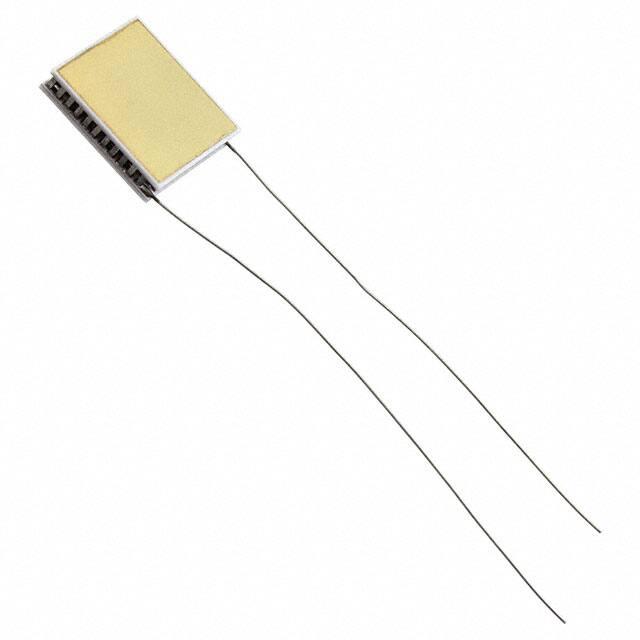
Technical Data Sheet
for NL1013T
Single-Stage Thermoelectric Module
PRODUCT FEATURES
•
•
•
•
•
•
RoHS EU Compliant
Rated operating temperature of 85°C.
Maximum processing temperature of 220°C.
Ceramic Material: Aluminum Oxide
Metallized Exterior Surfaces are Au flash, suitable for soldering.
RTV Sealing options available.
II-VI MARLOW
www.marlow.com
CONTACT US
marlow.sales@ii-vi.com– Dallas, TX USA
214-340-4900 – 877-627-5691
DOC #: 102-0292
REV: N
�NOMINAL PERFORMANCE IN NITROGEN
Hot Side Temperature (°C)
Δ Tmax (°C):
Qmax (watts):
Imax (amps):
Vmax (vdc):
AC Resistance (ohms):
27
61
4.8
1.0
8.5
7.42
OPERATION CAUTIONS
50
69
5.4
1.0
9.6
ORDERING OPTIONS
Model Number
NL1013T-02AC
NL1013T-03AC
NL1013T-04AC
NL1013T
For maximum reliability, storage and operation
below 85°C in a non-condensing environment is
recommended. To minimize thermal stress, use
linear/proportional temperature control or a
similar method rather than an ON/OFF method.
INSTALLATION
Description
TEM, Base Metallized Exterior
TEM, No Metallized Exterior
TEM, No Metallized Exterior, RTV
Sealed, Special Wires
Recommended mounting methods: Bonding with
thermal epoxy or soldering with metallized ceramics.
For additional information, please refer to our TEM
Installation Guide.
TYPICAL PERFORMANCE CURVES
ENVIRONMENT: 10^-5 TORR VACUUM
Hot Side Temperature: 27°C
HEAT
LOAD
(WATTS)
T (C)
40
20
0
8
6
4
2
0
0.0
Q=0
T=0
0.2
0.4
0.6
0.8
CURRENT (AMPS)
1.0
0.0
0.5
1.0
1.5
2.0
2.5
3.0
3.5
4.0
4.5
5.0
60
T (C)
0.0
0.5
1.0
1.5
2.0
2.5
3.0
3.5
4.0
4.5
60
HEAT
LOAD
(WATTS)
80
40
20
0
VOLTAGE (VDC)
80
VOLTAGE (VDC)
Hot Side Temperature: 50°C
8
6
4
Q=0
T=0
2
0
0.0
0.2
0.4
0.6
0.8
CURRENT (AMPS)
1.0
For performance information in a vacuum or with hot side temperatures other than 27°C or 50°C, contact one of our Applications
Engineers at 877-627-5691.
DOC #: 102-0292
MI Form 005-0685
Rev A
REV: N
2/4
�NL1013T
POWER GENERATION PERFORMANCE CURVES
Hot Side Temperature (°C)
70
75
85
0.5
0.025
0.4
0.02
0.3
0.015
0.2
0.01
0
1
0.9
0.8
0.7
0.6
0.5
0.4
0.3
0.2
0.1
0
0.7
0.6
Tc=50°C
0.03
0.005
η / Opt η
80
Power
0.3
0.5
0.7
0.9
1.1 1.3
Heat (W)
1.5
1.7
Normalized Off-Peak Performance
Efficiency
0
1
2
DOC #: 102-0292
MI Form 005-0685
Rev A
3
4
5
6
7
Load Resistance Ratio
REV: N
8
Voltage
1.9
0.1
0
1
0.9
0.8
0.7
0.6
0.5
0.4
0.3
0.2
Voltage 0.1
0
9
10
0.1
0.09
0.08
0.07
0.06
0.05
0.04
0.03
0.02
0.01
0
30 35 40 45 50 55
65
75
85
Tc=27°C
1.2
1
0.8
0.6
0.4
Opt Voltage (V)
65
Opt Power (W)
Opt Power (W)
0.035
60
Opt Voltage (V)
55
Voltage / VOC
0.04
Hot Side Temperature (°C)
0.2
Power
0.2
0.7
1.2
1.7
2.2
Heat (W)
Hot Side Temperature (°C)
Cold Side Temperature (°C)
Optimum Efficiency, η (%)
Optimum Power (W)
Optimum Voltage (V)
Load Resistance for Opt η (Ω)
Open Circuit Voltage, VOC (V)
Short Circuit Current (A)
Thermal Resistance (°C/W)
85
27
2.52
0.087
1.021
12.00
1.79
0.20
16.86
Voltage
2.7
3.2
55
27
1.28
0.021
0.487
11.20
0.85
0.10
16.88
35
27
0.37
0.002
0.138
10.65
0.24
0.03
16.85
0
3/4
�NL1013T
MECHANICAL CHARACTERISTICS
For customer support or general questions please contact a local office or visit our website at www.marlow.com.
Marlow reserves the right to make product changes without notice.
Power Generation performance information is given in a nitrogen environment and cold side temperatures of 27°C and 50°C.
Module temperature does not include thermal resistance of heat sinks. For performance information in vacuum, other cold side
temperatures, or specific heat sinks, consult one of our applications engineers.
TYPICAL POWER GENERATION CONFIGURATION
EXAMPLE:
(-)
(+)
Hot Side, Th
Cold Side, Tc
DOC #: 102-0292
MI Form 005-0685
Rev A
REV: N
4/4
�
很抱歉,暂时无法提供与“NL1013T-02AC”相匹配的价格&库存,您可以联系我们找货
免费人工找货