MTO-EV004(TB67S179FTG) 数据手册
Instruction manual
for Evaluation Board of TB67S179FTG
Aug 9, 2019
Rev.1.2
�【Outline】
The TB67S179 is a two-phase unipolar stepping motor driver using a PWM
chopper. The clock in decoder system and BiCD process are adopted. Rating of
80V and 1.5A is realized.
This evaluation board mounts necessary components to evaluate the IC. Each
excitation drive of full step, half step, quarter step, 1/8 step, 1/16 step, and 1/32
step can be run with PWM constant current drive. Please sense low noise and
low vibration of the stepping motor.
【Note】
In using, please be careful about thermal condition sufficiently.
As for each control signal, please refer to the IC specification by accessing to the
below URL.
http://toshiba.semicon-storage.com/us/product/linear/motordriver/detail.TB67S179FTG.html
Further, the application of this evaluation board is limited to the purpose of
evaluating and learning the motor control. Please do not ship them to a market.
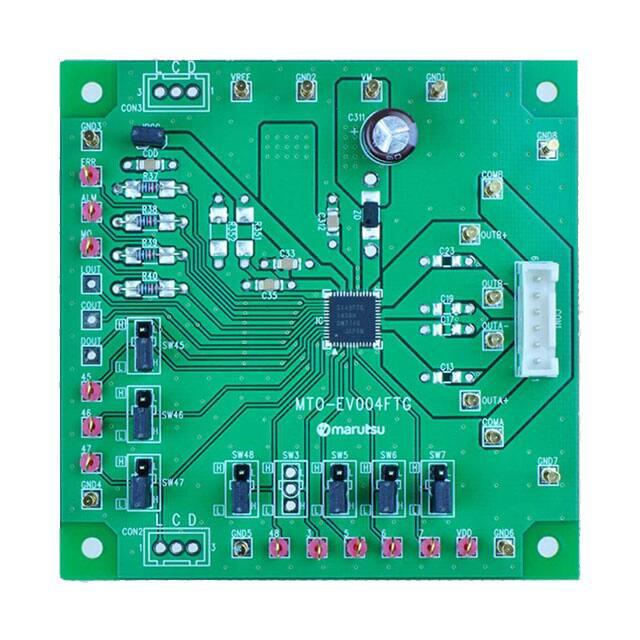
�Connection to Evaluation board
Reference voltage for
motor current set
Vref (0V to 3.6V)
(Note) Silk name and signal name on the
board are different because the series
products have the common board.
Silk name
ERR
ALM
MO
LOUT
COUT
DOUT
45
46
47
48
3
5
6
7
Signal name
ERR
ALM
MO
NC
NC
NC
DMODE0
DMODE1
DMODE2
RESET
CLK
ENABLE
CW/CCW
BRAKE
VrefB(for B-axis)
Power source of VM
(10V to 47V)
VM
GND
Two-phase unipolar type
Stepping motor
Corresponding table
(Silk name vs. Signal name)
�Setting evaluation board1
Setting motor current
Setting motor current
Iout(max) = Vref(V) x 3/4
Vref
R351
R352
Mounted
area
Vref can be generated from the internal
regulator (VCC) by mounting the divider
resistance to R351 and R352.
Please mount the divider resistance in
generating Vref from the internal regulator
(VCC).
R351: VCC side, R352: GND side
Relation between setting current and
waveform of motor drive current
Setting current
Motor current
(OUT(+))
Charge
Charge
Decay
Charge
Decay
Decay
(Fixed off time) (Fixed off time) (Fixed off time)
�Setting evaluation board2
Setting fixed off time
Setting constant current PWM control
Vref
The TB67S179 drives with constant current PWM control.
Fixed off time can be configured with pull-down resistance
which is connected to OSCM pin. The relation between the
pull-down resistance and the fixed off time is shown in the
below table. Please adjust by referring to it.
*The values in the table do not include variations in precision of
the IC and external parts. They are reference data.
*Please connect the standard resistance (10kΩ) even in the
constant voltage mode.
External
Fixed off time (toff)
resistance(ROSCM)
3.9kΩ
4.1µs
4.7kΩ
4.9µs
5.6kΩ
5.8µs
6.8kΩ
7.0µs
8.2kΩ
8.3µs
10kΩ
10µs
15kΩ
15µs
18kΩ
18µs
22kΩ
21µs
27kΩ
26µs
39kΩ
37µs
Relation between fixed off time and
waveform of motor drive current
Setting current
Motor current
(OUT(+))
Charge
Charge
Decay
Charge
Decay
Decay
(Fixed off time) (Fixed off time) (Fixed off time)
�(Reference) Waveform of motor drive
【When the next current step is higher
than the previous step
CLOCK input signal
【When the next current step is lower
than the previous step
CLOCK input signal
The next current step is below
Motor output current
Motor output current
モータ出力電流
the previous step, and the motor
current is above the new current
step, it will automatically switch
to decay sequence.
Charge term will change.
MO voltage (VCC pull up)
When the current threshold (current step) is
shifted to the next threshold (step), the
‘Charge’ time may change, but the ‘Decay
(=off time)’ time will not. (The off time
depends on the OSCM resistance.)
MO voltage (VCC pull up)
When the current step is shifted to the next
step: if the motor current is above the PWM
threshold, it will then go onto the decay
sequence. If the motor current is below the
next current step, it will continue on to the
constant current PWM.
�Setting evaluation board3
Setting motor operation
Fixed level by
jumper
JPCC
Jumper indicated in the left figure
is adopted on this evaluation
board to set operation of the
TB67S179FTG.
To select the function by the
jumper, short-circuit JPCC.
Fixed level of the silk near the
jumper is indicated inside the
white frame. Please change the
short position according to the
configuration of the usage
function.
In case of inputting the signal
externally, please remove the
short pin.
�Circuit of evaluation board
JPCC
VM
R38
R39
R40
C33
ZD
VREF
ERR
R351
ALM
R352
MO
R37
CON3
C311
C312
COMB
C35
36 35 34 33 32 31 30 29 28 27 26 25
39
22
40
21
41
20
IC mounted
area
42
DOUT
43
SW45
45
C23
23
C19
38
17
45
16
46
15
47
14
48
13
2
3
4
5 6
7
OUTB-
18
44
1
CON1
19
C17
COUT
24
OUTA-
C13
LOUT
OUTB+
37
OUTA+
8 9 10 11 12
SW46
COMA
46
SW47
CON2
48
3
5
SW7
SW6
SW5
SW3
SW48
47
6
7
�◆ Important Note ◆
●This product was not designed for use with devices which could cause
personal injury in the event of failure or malfunction, including devices for
use in areas including medical, military, aviation, aerospace, nuclear control,
other types of safety mechanisms, etc., or for use in devices which require a
high standard of safety. Do not use this product for such applications. This
company assumes no liability for damages which may result from use of the
product.
Manufactured and Distributed by
https://www.marutsu.com
Marutsuelec Co., Ltd.
5-2-2, Seiki Daiichi Building 7F, Sotokanda, Chiyoda-ku,
Tokyo 101-0021, Japan
Tel:+81-3-6803-0209 FAX:+81-3-6803-0213
�
MTO-EV004(TB67S179FTG) 价格&库存
很抱歉,暂时无法提供与“MTO-EV004(TB67S179FTG)”相匹配的价格&库存,您可以联系我们找货
免费人工找货