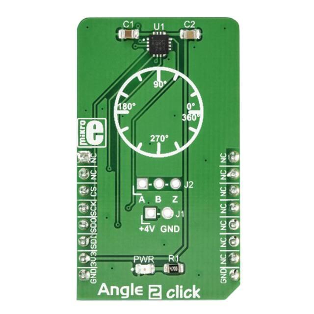
Angle 2 Click
PID: MIKROE‐2338
Weight: 23 g
Angle 2 click is a magnetic rotational sensor which relies on the ultra-fast MA700
angular sensor IC. Due to a high data output rate of 500kHz, the MA700 IC is able to
provide a reliable absolute angular positional data at speeds up to 100,000 RPM. This
can be achieved by utilizing the advanced Spinaxis technology based on a direct angle
sampling approach, instead of using the extensive arctangent computations and other
similar solutions. This also allows for relaxed mechanical tolerances, allowing even the
off-axis magnetic field to be used.
It comes in the package which also includes the mikroSDK™ software and a library with
all the functions. The Click board™ comes as a fully tested and approved prototype,
making it a reliable device ready to use on the development board.
�Besides the standard SPI interface used to interface with the host MCU, the MA700
sensor IC features the quadrature encoded outputs so that it can directly replace similar
mechanical devices. The advantages of a contactless quadrature encoder are many,
therefore Angular 2 click is equipped with a three-pin header, offering an easy access to
these outputs. An OTP memory can be utilized to permanently store application-specific
settings, such as the zero-angle position. Features such as the low-latency angular data
acquisition, high reliability of the Spinaxis technology, the embedded quadrature
encoder outputs, make the Angle 2 click a perfect solution for various applications that
require a reliable angle sensing. It can be used for servo drives, in various robotic and
automotive applications, for the BLDC motor speed detection, as the mechanical
quadratic encoder replacement, and more.
How does it work?
Angle 2 click is based on the MA700 IC, an angular sensor for position control with sideshaft positioning capability, produced by Monolithic Power Systems (MPS). This IC has a
set of features, critical for high-speed angular position sensing applications: it utilizes
the Spinaxis frontend that allows very fast data output rates up to 500kHz, and a very
low-latency data output, down to 3 µs, even when using the data filtering and
conditioning options. This makes it suitable for measuring the angle of the motor shaft
in various high-speed applications, such as BLDC motor applications. It can be used at
speeds up to 100,000 RPM, still retaining its accuracy.
The magnetic field is only sensed along the horizontal (XZ) plane by utilizing an array of
aligned Hall sensors. This allows sampling of the absolute angular position of a
diametrically magnetized cylinder, typically attached at the end of the rotor shaft. Unlike
�some other methods, the Spinaxis does not require heavy mathematical calculations, as
it is based on the phase detection, directly digitizing the magnetic field direction. This is
the key to an extremely low output latency of 3µs. This also allows very accurate angular
position reading, as the actual physical angle coincidences with the 11-bit data available
at the output, due to practically no conversion delay. The Spinaxis frontend also allows
off-axis placement of the permanent magnet, as the MA700 features built-in
linearization for the side-shaft mounting in a form of an offset register. This relaxes the
mechanical demands of the user application.
The incremental quadrature encoder function uses three output pins: A, B, and Z. The A
signal pulses 256 times during a full revolution. The B signal is shifted by a quarter of
the pulse period, depending on the direction of the rotation. The application can use
this fact to determine the direction of the rotation. The Z signal pulses once per 360°.
The pulses on A and B outputs are affected by jitter, which can cause the output to be
inconsistent if used at speeds over 30,000 RPM. For high-speed applications, using the
SPI interface is recommended. The A, B, and Z pins of the MA700 IC are routed to a
standard, 2.54 mm (0.1 inches) pitch 1x3 header, mounted on the Angle 2 click, so it can
be easily accessed by an external application.
The MA700 also features the one-time programmable (OTP) memory, which allows the
working parameters of the IC to be stored as the default values. This allows a lot of
flexibility for a project design since the factory pre-flashed default values might not
always fit the requirements of the specific application. A typical example might be the
zero-position configuration: if the sensor must be fixed to a certain angle which has to
be the start position for the angle counting (the zero angle), the user application would
have to internally re-calculate values to compensate, introducing more latency. The
ability to define own default settings is certainly a useful option. However, flashing the
OTP memory is a sensitive process, as there is very little room for an error (being onetime programmable). The datasheet of the MA700 offers a detailed guide for flashing
the OTP, while Angle 2 click offers an external power supply (PSU) connector,
implemented as the standard 2.54mm 1x2 header. The OTP flashing requires a separate
PSU of 4V to be used.
The SPI communication consists of the read/write (R/W) command, an address of the
register, and the data. The R/W command and the address are two 4-bit values, while
the data is a single 8-bit value. The MA700 datasheet contains the detailed information
on all the commands, however, Angle 2 click comes with the library that contains very
simplified angle reading functions, as well as the functions used for an easy configuring
of the Angle 2 click. The MA700 SPI pins are routed to the respective pins of the
mikroBUS™, allowing easy and reliable interfacing with the host MCU.
�Specifications
Type
Magnetic
An ideal solution for a wide variety of contactless angle measurement
Applications
applications. It can be used for servo drives, in various robotic and
automotive applications, for the BLDC motor speed detection, as the
mechanical quadratic encoder replacement, and more
On-board
MA700 IC, an angular sensor for position control with side-shaft positioning
modules
capability, produced by Monolithic Power Systems (MPS)
Accurate sensing of the magnetic angle at up to 100,000 RPM, good linearity
Key Features
and low error margin even when used with the off-axis magnets, latency-free
Spinaxis technology, OTP memory for permanent storing of the default
parameters, etc.
Interface
SPI
Input Voltage
3.3V
Click board
size
M (42.9 x 25.4 mm)
Pinout diagram
This table shows how the pinout on Angle 2 Click corresponds to the pinout on the
mikroBUS™ socket (the latter shown in the two middle columns).
Notes
Pin
NC
Pin
1
AN
PWM
16
NC
Notes
�NC
2
RST
INT
15
NC
CS
3
CS
RX
14
NC
SCK
4
SCK
TX
13
NC
SPI Data OUT
SDO
5
MISO
SCL
12
NC
SPI Data IN
SDI
6
MOSI
SDA
11
NC
Power supply
3.3V
7
3.3V
5V
10
NC
Ground
GND
8
GND
GND
9
GND
SPI chip Select
SPI Clock
Ground
Onboard settings and indicators
Label
Name
Default
Description
PWR
PWR
-
Power LED indicator
J1
-
Left
Power supply for the OTP programming (4V)
J2
-
-
A, B, Z quadrature encoder outputs
Software support
We provide a library for the Angle 2 click on our LibStock page , as well as a demo
application (example), developed using MikroElektronika compilers. The demo can run on
all the main MikroElektronika development boards.
�Library Description
The library can perform a control of the Angle 2 Click board. Also can measure the angle
value in degrees with a range of 0 deg to 359.91 deg. Zero position setting also can be
performed by using this library. The library offers a choice to save content of an entire
selected register in OTP memory. For more details check documentation.
Key functions:
T_ANGLE2_DEG_VAL angle2_writeReg( uint8_t regAddr, uint8_t dataIn ) - Function
writes one byte data to the register.
T_ANGLE2_DEG_VAL angle2_getAngle( void ) - Function returns angle value in degrees with
a range from 0 to 359.91.
void angle2_setZeroScale( T_ANGLE2_DEG_VAL zeroDeg ) - Function sets a zero position
value in degrees with 12-bit resolution.
Examples description
The application is composed of the three sections :
System Initialization - Initializes peripherals and pins.
Application Initialization - Initializes SPI interface in Mode 3 and performs a device configuration
for properly working.
Application Task - (code snippet) - Reads angle value in degrees and logs results on uart
terminal.
void applicationTask()
{
angle = angle2_getAngle();
FloatToStr( angle, text );
floatCut();
mikrobus_logWrite( "Angle is: ", _LOG_TEXT );
mikrobus_logWrite( text, _LOG_TEXT );
mikrobus_logWrite( " deg", _LOG_LINE );
Delay_ms( 200 );
}
Additional Functions :
void floatCut() - Makes float value to be rounded on two decimal places.
�The full application code, and ready to use projects can be found on our LibStock page.
Other mikroE Libraries used in the example:
Conversions
SPI
UART
Additional notes and information
Depending on the development board you are using, you may need USB UART
click, USB UART 2 click or RS232 click to connect to your PC, for development systems
with no UART to USB interface available on the board. The terminal available in all
MikroElektronika compilers, or any other terminal application of your choice, can be
used to read the message.
mikroSDK
This click board is supported with mikroSDK - MikroElektronika Software Development
Kit. To ensure proper operation of mikroSDK compliant click board demo applications,
mikroSDK should be downloaded from the LibStock and installed for the compiler you
are using.
For more information about mikroSDK, visit the official page.
https://www.mikroe.com/angle‐2‐click/12‐6‐18
�