BarGraph 2 click
PID: MIKROE‐3021
Weight: 36 g
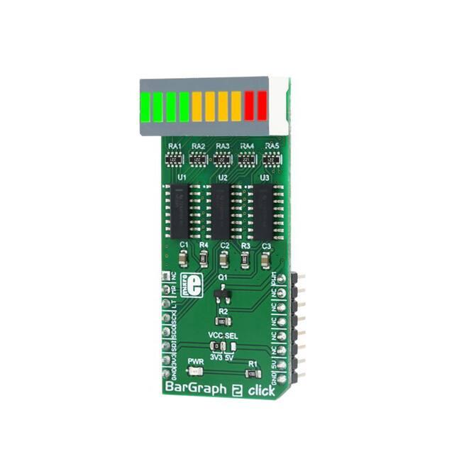
BarGraph 2 click is a 10‐segment bar graph display click, which uses a high‐quality,
multicolor bar graph LED display. The bar graph display is a very popular device for
displaying various properties, whether it be an audio level, current/voltage level, position
of the encoder, and generally any property that can be displayed in a form of a bar graph.
The segments of the on‐board bar graph LED display are bright and uniformly colored,
providing a nice and clean visual feedback.
Each segment is composed of green and red colored LEDs, making it possible to have
various important states marked in different color. It can use green, red, and a combination
of these two ‐ resulting in having amber colored segments. For example, a VU‐meter can
have its highest values shown in red (peaks), middle in yellow and the lowest in green; the
position of the encoder can be marked with a single red segment, on a green background,
and so on. The bar graph display light intensity can be dimmed, by applying a PWM signal.
The Click board™ offers a lot of possibilities for building a custom bar graph applications ‐
VU meters, status indicators, various types of gauges, and similar.
�How does it work?
When it comes to driving an array of LED segments, using so‐called shift register ICs is
almost unavoidable. Due to their ability to be connected in cascades, they are commonly
used for any type of LED segment array. This Click board™ uses three 74HC595, 8‐bit
serial‐in, parallel‐out shift registers with output latches, from Texas Instruments to drive
the XGURUGX10D, a 10 segment bar graph array, from SunLED. The 74HC595 ICs are
comprised of a D‐type internal storage register, as well as the serial‐to‐parallel shift
register, both 8 bits wide. Each of these registers has its own clock line, making it possible
to clock in the desired data, and then clock it out to the parallel output pins.
The XGURUGX10D bar graph LED array has 10 dual‐color segments. Each segment contains
red and green LED, thus having two anodes and one cathode per segment. This results in
having 20 LED anodes and 10 LED cathodes, in total. The XGURUGX10D bar graph display
is connected as a common cathode type display, meaning that all LED cathodes are routed
to a single point. The LED cathode line is connected to the drain of the N channel MOSFET,
while its source is connected to the GND. Driving this MOSFET via its gate through the PWM
pin of the mikroBUS™ allows dimming of the LED segments. By changing the duty cycle of
the PWM signal, it is possible to change the brightness of the XGURUGX10D bar graph
display.
The Click board™ communicates with the host MCU via the SPI interface, routed to the
mikroBUS™ MOSI, MISO and SCK pins, labeled as SDI, SDO and SCK on this Click board™,
respectively. Three bytes of information (24 bits in total) are pushed through the serial
data input pin (DS) of the first 74HC595 IC, routed to the SDI pin. The 74HC595
construction is such that after receiving 8 bits, clocking in one more bit will shift the
existing 8 bits by one place, overflowing the last bit to the Q7S output pin, shifting it out
that way. Since the Q7S of the first 74HC595 is connected to the DS pin of the second
�74HC595 (and the Q7S of the second IC is connected to the DS pin of the third 74HC595 IC),
clocking in 24 bits to the first 74HC595 IC will fill up all three ICs.
It is worth mentioning that the Q7S of the last 74HC595 IC is routed to the MISO pin of the
mikroBUS™, labeled as the SDO, allowing connection of multiple devices in cascade,
building more complex setups. Adding more devices in cascade would require more 8bit
words to be clocked in the first 74HC595 IC.
The first 10 bits are used to control all the green LEDs of the segments. The second 10 bits
are used to control all the red LEDs of the segments. Since the MCU usually clocks out no
less than 8 bits through the SPI per cycle, the last 4 bits of the total of 24 bits, are
disregarded. When the data has been clocked in, the SPI clock should stop and the CS pin
should be driven to a HIGH logic level. The CS pin of the mikroBUS™ is routed to the STCP
pin of the 74HC595 ICs, and it is labeled as LT. A rising edge on the STCP input pins of the
74HC595 ICs will latch the data from their internal storage registers to the output pins,
polarizing the connected bar graph segment anodes. The STCP pin is pulled to a LOW logic
level by the onboard resistor.
The #MR pin is used to clear the data in the internal storage register of the ICs. The LOW
logic level on this pin will clear the content of this storage register, but it will not turn off
the outputs which are already activated. The #MR pin is routed to the RST pin of the
mikroBUS™, labeled as MR and it is pulled to a HIGH logic level by the onboard resistor.
BarGraph 2 click is able to work with both 3.3V and 5V MCUs. The operating voltage
selection can be done via the onboard SMD jumper, labeled as VCC SEL.
Specifications
Type
LED Segment
It can be used for displaying of various signal or status properties,
Applications
for building VU-meters, and various types of gauges and signal
indicators
On-board
modules
Key Features
74HC595, 8-bit serial-in, parallel-out shift registers with output
latches, from Texas Instruments; XGURUGX10D, a 10 segment
bargraph array, from SunLED
Clean and bright bargraph dual-color LED display, with uniform
�light disbursement, simple to use with included software library
functions
Interface
PWM,SPI
Input Voltage
3.3V or 5V
Click board
size
L (57.15 x 25.4 mm)
Pinout diagram
This table shows how the pinout on BarGraph 2 click corresponds to the pinout on the
mikroBUS™ socket (the latter shown in the two middle columns).
Notes
Pin
Pin
Notes
NC
1
AN
PWM
16
PWM
Clear input IN
MR
2
RST
INT
15
NC
Latch input IN
LT
3
CS
RX
14
NC
SPI Clock
SCK
4
SCK
TX
13
NC
SPI Data OUT
SDO
5
MISO
SCL
12
NC
SPI Data IN
SDI
6
MOSI
SDA
11
NC
+3.3V
7
3.3V
5V
10
+5V
Power supply
GND
8
GND
GND
9
GND
Ground
Power supply
Ground
Dimming PWM IN
�Onboard settings and indicators
Label
Name
Default
LD1
PWR
-
JP1
VCC SEL
Right
Description
Power LED indicator
Power supply voltage selection: left position 3.3V, right
position 5V
Software support
We provide a library for BarGraph 2 click on our Libstock page, as well as a demo
application (example), developed using MikroElektronika compilers. The demo application
can run on all the main MikroElektronika development boards.
Key functions:
bargraph2_write(uint8_t regValue);- Generic write function
void bargraph2_reset();- Bargraph reset
void bargraph2_set(uint8_t value);- Sets the bargaph LEDs
Examples Description
System Initialization - GPIO and SPI module initialization
Application Initialization - SPI driver initialization
Application Task - Turning all 10 LED ON sequentially on the bargraph
void applicationTask()
{
for (i = 0; i