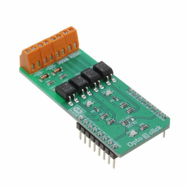
Opto 3 click
PID: MIKROE‐3319
Weight: 28 g
Opto 3 click is a relay Click board™, equipped with two pairs of optically
isolated solid-state relays (SSR). One pair of SSRs is used to provide a
reinforced galvanic isolation for the external signals used to drive the
microcontroller (MCU) pins, while the other pair of SSRs is used to allow the
host MCU to drive some external equipment, allowing up to 40V between the
SSR contacts in OFF state, and currents up to 2A while in ON state, thanks
to a very low ON-state resistance. Opto 3 click to be used in applications
that require reinforced galvanic isolation for both their input and output
stages.
�Opto 3 click is supported by a mikroSDK compliant library, which includes
functions that simplify software development. This Click board™ comes as a
fully tested product, ready to be used on a system equipped with the
mikroBUS™ socket.
Featuring good quality TLP241A SSRs, this Click board™ represents an ideal
solution for development of various PLC-based applications, where it can be
used as a replacement for mechanical relays, bringing the whole range of
inherited benefits: no mechanical parts which can wear off, constant ONstate resistance, immunity to environmental influences and mechanical
shock, no contact bouncing effect, and more. Two onboard LEDs provide
visual feedback on the state of the output SSR pair, while the input SSR pair
is protected from inverse polarization and the damage it may cause, by low
voltage drop Schottky diodes.
How does it work?
Opto 3 click features two pairs of normally opened, high-quality solid-state
relays labeled as TLP241A, by Toshiba. The TLP241A is an optically isolated
solid-state relay (SSR), featuring an integrated IR LED and two output
MOSFETs. The output stage does not have any electrical contact with the
input stage; it is activated by infrared light, produced by an integrated IR
LED. This allows reinforced galvanic isolation between the input and the
output stage. The output stage can sustain up to 40V while OFF. When
activated, due to a very low RDSON of the integrated MOSFETs, it can
conduct up to 2A of current.
�The TLP241A are able to effectively replace traditionally used mechanical
relays, bringing up the full set of inherited benefits: virtually unlimited
number of cycles since there are no moving parts that would wear off, no
bouncing effect on the output contacts, high resistance to mechanical shock
and environmental influence, low current required for the activation,
constant resistance since no carbon and rust can build up on contacts, there
is no sparking or electric arc forming while operated, compact size, higher
isolation voltage, and so on. However, unlike optocouplers (similar devices
which are designed for much lower currents and voltages), SSRs are not
designed to be used as signal line isolators. SSR typically has a slow signal
propagation time. Still, it can be used for various communication protocols
which use lower data rates, including UART/RS232, 1-Wire, and similar.
One pair of SSRs is driven by the host MCU. This pair can be used to activate
an external circuit, utilizing the full potential of the TLP241A SSR. One or two
SSRs can be used as relays, allowing the host MCU to control heavier loads
such as DC motors, some other electrical circuit which operates on higher
potential, LED strips, LED arrays, etc. A HIGH logic level on mikroBUS™ pins
AN or RST labeled as OU1 and OU2 respectively, will activate the integrated
IR LED. It will turn ON the MOSFETs in the SSR, allowing the current to flow
through an external circuit. Two red LEDs, labeled as OUT1 and OUT 2, are
connected to each of the MCU output pins. These LEDs provide visual
feedback about the SSR state: if ON, the respective SSR is in a conductive
state. SSR outputs are routed to two screw terminals labeled as OUT1 and
OUT2, allowing an external circuit to be securely connected.
The other pair of SSRs is used to provide optical isolation for external
signals, offering protection for sensitive MCU pins that way. While the SSR is
not activated, PWM and INT pins of the mikroBUS™ labeled as IN1 and IN2
respectively, are pulled to a HIGH logic level by a resistor. A signal on the
input terminal will activate the respective SSR, pulling the IN1 (IN2) pin to a
LOW logic level. Since galvanically isolated, the signal at the input terminal
can be at a different potential than the host MCU, preventing any stray
currents to flow between two GNDs. This will also protect the host MCU from
the electrostatic discharge (ESD) that might occur. It is important to connect
the input signal correctly. Therefore, two input terminals have their ports
clearly labeled with + and - signs. A Schottky diode in series provides some
protection to the input IR LED, however, care should be taken not to exceed
specifications from the TLP241A datasheet.
Pull-up resistors on the input side SSRs are connected to the power supply
from mikroBUS™, providing a HIGH logic level while the SSR is not active.
The voltage of the power supply directly determines the voltage level that
will be applied to IN1 and IN2 pins in this case. Therefore, an SMD jumper
�labeled as VCC SEL is provided on the Click board™, allowing the user to
select the logic voltage level between 3.3V and 5V, depending on the used
MCU and its capabilities.
Specifications
Type
Optocoupler
Applications
This Click board™ represents an ideal solution for development
of various PLC-based applications, where it can be used as a
replacement for mechanical relays, bringing the whole range
of inherited benefits
On-board
modules
TLP241A, a solid-state photo-relay by Toshiba
Key Features
One input and one output pair of high-quality SSRs,
reasonably high current and voltage on the output side, low
driving current, two LEDs for visual feedback of the output
stage, protection diodes on the input side, the whole range of
inherited benefits, typical for SSRs, etc.
Interface
GPIO
Input
Voltage
3.3V or 5V
Click board
size
M (42.9 x 25.4 mm)
�Pinout diagram
This table shows how the pinout on Opto 3 Click corresponds to the pinout on
the mikroBUS™ socket (the latter shown in the two middle columns).
Notes
Pin
Pin
Notes
Relay 1 OUT
OU1
1
AN
PWM
16
IN1
Relay 1 IN
Relay 2 OUT
OU1
2
RST
INT
15
IN2
Relay 2 IN
NC
3
CS
RX
14
NC
NC
4
SCK
TX
13
NC
NC
5
MISO
SCL
12
NC
NC
6
MOSI
SDA
11
NC
Power Supply
+3V3
7
3.3V
5V
10
+5V
Power Supply
Ground
GND
8
GND
GND
9
GND
Ground
Onboard settings and indicators
Label
Name
Default
Description
LD1
OUT1
-
OUT1 Activity LED indicator
LD2
OUT2
-
OUT2 Activity LED indicator
LD3
PWR
-
Power LED indicator
�Logic voltage level selection: left position
3.3V, right position 5V
JP1
VCC SEL
Left
CN1,
CN2
IN1, IN2
-
Input connectors
CN3,
CN4
OUT1, OUT2
-
Output connectors
Opto 3 click electrical characteristics
Description
Min
Typ
Max
Unit
Input forward current (IF)
5
7.5
25
mA
Peak transient input forward current (IFPT)
-
-
2
A
Output current (IO)
-
-
32
V
-20
-
+65
Operating temperature
Software support
We provide a library for the Opto 3 Click on our LibStock page, as well as a
demo application (example), developed using MikroElektronika compilers. The
demo can run on all the main MikroElektronika development boards.
Library Description
The library performs the input state checking and the output state setting.
For more details check documentation.
Key functions:
T_OPTO3_STATE opto3_getIN1( void ) - Function returns a state of the Input 1.
�
void opto3_setOUT2( T_OPTO3_SWITCH state ) - Function puts the Output 2 to the desired
state.
Examples description
The application is composed of the three sections :
System Initialization - Initializes peripherals and pins.
Application Initialization - Initializes GPIO interface.
Application Task - (code snippet) - Switches ON or switches OFF the both outputs depending
on the states of the inputs, respectively. Note : Input state is active low, and output state is
active high.
void applicationTask()
{
stateIN1 = opto3_getIN1();
stateIN2 = opto3_getIN2();
stateOUT1 = stateIN1 ^ 1;
stateOUT2 = stateIN2 ^ 1;
opto3_setOUT1( stateOUT1 );
opto3_setOUT2( stateOUT2 );
}
The full application code, and ready to use projects can be found on
our LibStock page.
Additional notes and informations
Depending on the development board you are using, you may need USB UART
click, USB UART 2 click or RS232 click to connect to your PC, for development
systems with no UART to USB interface available on the board. The terminal
available in all MikroElektronika compilers, or any other terminal application
of your choice, can be used to read the message.
https://www.mikroe.com/opto‐3‐click/2‐13‐19
�