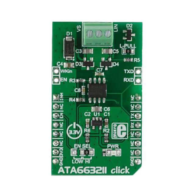
ATA663211 click
PID: MIKROE-2335
Weight: 35 g
ATA663211 click carries an Atmel LIN transceiver IC designed to handle low-speed
data communication in vehicles and in industrial applications with electrically harsh
environments. The LIN connection is established by attaching wires to the onboard
screw terminals.
The click communicates with the target MCU through the UART interface and runs on a 3.3V
power supply.
ATA663211 click can aslo be used as a standalone LIN transceiver, without being connected to a
mikroBUS™ socket. An onboard LDO (low-dropout regulator) enables it to get its power supply
through the VS line screw terminal.
�LIN transceiver
LIN or Local Interconnect Network is a protocol used for communicating between components
in vehicles. These days cars have hundreds of sensor applications to measure things like
temperature, pressure, air flow, speed, etc. All these applications need to communicate with the
main system.
The LIN bus was created by European car manufactures in order to establish a new, uniform
communication standard. It can be used with CAN (Controller Area Network), but LIN is more
cost-effective for simple sensor networks in vehicles.
For more information see our Learn article on the LIN network protocol.
Low current consumption
The IC has three very low power modes: normal, sleep and fail-safe. In sleep mode the current
consumption is typically 9μA – this is the lowest current consumption mode. It automatically
switches to fail-safe mode at system power-up or after a wake-up event. In fail-safe mode it
typically uses 80μA.
Applications
Automotive industry and other electrically harsh environments.
Key features
Atmel ATA663211 IC
o Compliant with LIN 2.0, 2.1, 2.2, 2.2A and SAEJ2602‐2
o Data communication up to 20Kbaud
o Power consumption 9μA in sleep mode
o Bus pin is over‐temperature and short‐circuit protected
o Interference and damage protection according to ISO7637
Can be used as a standalone device
Screw terminals for LIN connection
LDO for regulating external power supply
3.3V power supply
�Type
LIN
Applications
Automotive industry and other electrically harsh environments
On-board
modules
Atmel LIN transceiver IC
Key Features
Data communication up to 20Kbaud, Power consumption 9μA in sleep mode,
Bus pin is over-temperature and short-circuit protected
Key Benefits
Can be used as a standalone device, LDO for regulating external power supply
Interface
UART
Power Supply
3.3V
Compatibility
mikroBUS
Click board size M (42.9 x 25.4 mm)
What does a LIN transceiver do
LIN or Local Interconnect Network is a protocol used for communication between components
in vehicles. The car industry has changed profoundly during this century. Cars have hundreds of
sensor applications to measure things like temperature, pressure, air flow, speed, etc. All these
applications need to communicate with the main system. The LIN bus was created by European
car manufactures in order to establish a new, uniform communication standard. It can be used
with CAN (Controller Area Network), but LIN is more cost-effective for simple sensor networks
in vehicles.
But what is the difference between LIN and CAN network protocols? CAN is an a really
complex interface, and with so many electronic components in a car the manufactures needed a
cheaper alternative. The LIN interface is simpler than CAN — LIN uses a single wire
communication and the slave nodes are clocked by only one master. CAN interface has nodes
that can act independently, receive messages and act. It can have more than one master on the
CAN bus. A LIN network is usually made of up to 16 nodes - one master and 15 slaves. This
serial communications protocol is also well suited for other industrial applications with
electrically harsh environments.
Screw terminals
The click has three screw terminals: VS line for the power supply (up to 40V), GND for ground
and LIN line for connecting to the other transceiver LIN line.
�Maximum Ratings
This table shows how the pinout on Grid-EYE click corresponds to the pinout on the
mikroBUS™ socket (the latter shown in the two middle columns).
Description
Min
Typ
Max
Unit
Supply voltage VS
-0.3
/
+40
V
Logic pins voltage levels (RxD, TxD, EN,NRES)
-0.3
/
+5.5
V
Logic output DC currents
-5
/
+5
mA
LIN
- DC voltage
- Pulse time < 500ms
-27
/
+40
+43.5
V
V
INH
-DC voltage
-0.3
/
Vs+0.3
V
WKin voltage levels
- DC voltage
-Transient voltage according to ISO7637
(coupling 1nF), (with 2.7K serial resistor)
-0.3
-150
/
+40
+100
V
ESD according to IBEE LIN EMC
Test specification 1.0 following IEC 61000-4-2
- Pin VS, LIN to GND, WKin (with ext. circuitry acc. applications
diagram)
+-6
ESD HBM following STM5.1
with 1.5kW/100pF
- Pin VS, LIN, INH to GND
- Pin WKin to GND
+-6
+-5
HBM ESD
ANSI/ESD-STM5.1
JESD22-A114
AEC-Q100 (002)
+-3
kV
kV
kV
�CDM ESD STM 5.3.1
Machine Model ESD
AEC-Q100-RevF(003)
+750
+200
V
V
Junction temperature
+150
C
+150
C
Storage temperature
-55
Pinout diagram
This table shows how the pinout on ATA663211 click corresponds to the pinout on the
mikroBUS™ socket.
Notes
Pin
Pin
Notes
mikroBUStm
controls an external voltage
regulator
INH
1
AN
PWM
16
NC
Not connected
Not connected
NC
2
RST
INT
15
NC
Not connected
controls the operating mode of the
device
EN
3
CS
TX
14
RX
UART
Transmit
Not connected
NC
4
SCK
RX
13
TX
UART
Receive
Not connected
NC
5
MISO
SCL
12
NC
Not connected
Not connected
NC
6
MOSI
SDA
11
NC
Not connected
�+3.3V power input
+3.3V
7
3.3V
5V
10
NC
Ground
GND
8
GND
GND
9
GND
Not connected
Ground
Additional pins and jumpers
In addition to mikroBUS the click has four additional pins:
WKIN — high‐input voltage pin used to wake up the device from sleep mode.
EN — controls the operating mode of the device.
TXD and RXD — additional UART transmit and receive lines.
EN SEL jumper enables pin selection mode (by default it is always on, good for standalone purposes)
otherwise can be LOW ‐ then it is connected to EN pin on the mikroBUS.
Programming
Maximum baud rate which achieved with 2 meter long cable is 19200 bps. Supported compilers
C : ARM AVR FT90x PIC PIC32 The following code snippet shows a simple routine which
prints received data on a terminal. Any time a click board receives 8 bytes of data it will print
received data on another UART. In this case UART3 is used for ATA663211 and UART1 is
used to log data.
1 void main()
2 {
3
system_init();
4
5
while( 1 ) {
6
7
if( Button( &GPIOA_IDR , 5, 100, 1 ) ){
8
ata663211_send( TX_DATA, sizeof( TX_DATA ) );
9
UART1_Write_Text( "Data Sent" );
10
}
11
12
if( ( chk = ata6563_rdy() ) == 8 ){
13
ata663211_read( buf, chk );
14
UART1_Write_Text( buf );
15
}
16
}
17 }
https://shop.mikroe.com/click/interface/ata663211 6-13-17
�
很抱歉,暂时无法提供与“MIKROE-2335”相匹配的价格&库存,您可以联系我们找货
免费人工找货- 国内价格
- 1+172.30735
- 5+168.86037