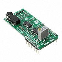
EMG click
PID: MIKROE-2621
EMG click measures the electrical activity produced by the skeletal muscles. It carries MCP609
operational amplifier and MAX6106 micropower voltage reference. EMG click is designed to run on a 5V
power supply. The click board™ has an analog output (AN pin).
Note: EMG click is a prototyping tool, not a medical‐grade device. Do not use it to diagnose patients.
�What is EMG?
Electromyography or EMG is a diagnostic technique for measuring the electrical activity of
muscles. It is often used to diagnose the health of these muscles, and the neurons that control
them. These neurons are called motor neurons. They transmit electrical signals, and the muscles
contract when this happens.
An EMG collects these signals and translates them into a graphical representation.
How EMG click works
The onboard 3.5mm audio jack is used to connect cables/electrodes to the click board. The
electrode collects voltage from the skin (few millivolts). And the signal from the jack is
amplified and filtered. Therefore, EMG click can be divided into seven blocks.
Setup guide
To record an EMG, you will need the following things:
1. EMG click
2. ECG/EMG cable
3. Disposable adhesive pads (sold in packs of 30)
If you are starting out, the best offer is the EMG click bundle that contains all three.
Of course, you will also need a target board with an MCU with at least a 10‐bit ADC (preferably powered
�from an external battery). Sampling rate should be at least 256Hz.
The electrodes are connected to the board with a cable that plugs into the onboard 3.5mm phone jack.
For optimal results place the first DRL electrode on the wrist of the hand. Place the second and
third electrode on the muscle you want to measure. See the image above.
MikroPlot application
MikroPlot is a free data visualization tool (Windows) that can be used to generate an EMG
graph. It’s a simple tool to help you visualize sensor data recorded over time.
The graph is generated from data sent from the microcontroller. A UART-USB connection is
required.
MCP609 features
The MCP606/7/8/9 family of operational amplifiers (op amps) from Microchip Technology Inc.
are unity-gain stable with low offset voltage (250 µV, maximum). Performance characteristics
include rail-to-rail output swing capability and low input bias current (80 pA at +85°C,
maximum).
MAX6106 features
The MAX6106 is a low-cost, low-dropout (LDO), micropower voltage reference. This threeterminal reference is available with output voltage options of 1.25V, 1.8V, 2.048V, 2.5V, 3V,
4.096V, 4.5V, and 5V. For this click, we used the 2.048V.
Key features
MCP609 amplifier
MAX6106 voltage reference
3.5mm audio jack
Interface: AN pin
5V power supply
�
SPECIFICATION
Type
Applications
On-board modules
Key Features
Interface
Power Supply
Compatibility
Click board size
Biomedical
Measuring the electrical activity produced by skeletal muscles.
MAX6106 voltage reference, 3.5mm audio jack
ESD protection, Overvoltage protection, High-pass filter
Analog
5V
mikroBUS
L (57.15 x 25.4 mm)
Pinout diagram
This table shows how the pinout on EMG click corresponds to the pinout on the mikroBUS™
socket (the latter shown in the two middle columns).
Notes
Pin
Pin
Notes
mikroBUStm
Analog output AN 1 AN
PWM 16 NC Not connected
Not connected NC 2 RST
INT 15 NC Not connected
Not connected NC 3 CS
TX 14 NC Not connected
Not connected NC 4 SCK
RX 13 NC Not connected
Not connected NC 5 MISO SCL 12 NC Not connected
Not connected NC 6 MOSI SDA 11 NC Not connected
Not connected NC 7 3.3V
5V 10 +5V Power supply
Ground GND 8 GND GND 9 GND Ground
�Jumpers and settings
Designator Name
ADC
ref.
JP1
Default
Position
Left
Default
Option
2.048
Description
Output voltage range, left position 0‐2.048V, right
position 0‐4.096V.
There is one SMD (0805) jumper that determines the output voltage range. When you connect all
three electrodes to each other, the output should be constant voltage (1.024V or 2.048V
depending on the jumper position). That constant voltage is zero-voltage on graphic, so the
positive part of EMG waveform will go above zero and negative part of the EMG waveform will
go below zero. There is also trimmer potentiometer which adjust the gain. So, if we set jumper to
2.048 position (zero is now 1.024V) that means that the gain should be set so that the EMG
waveform is in the range of 0-2.048V. If we set jumper to 4.096 position (zero is now 2.048V)
gain should be set so that the EMG waveform is in the range of 0-4.096V. So, jumper and
trimmer potentiometer are used to make output voltage level from EMG click accommodate to
the input voltage level of ADC which will be used.
LEDs and buttons
Designator Name Type
LD1
Description
PWR LED Power Supply Indication LED
How it works
The onboard 3.5mm audio jack is used to connect cables/electrodes to the click board. The
electrode collects voltage from the skin (few millivolts). And the signal from the jack is amplified
and filtered. Therefore, EMG click can be divided into seven blocks.
1. Protection ‐ Provides ESD protection (protects click), Overvoltage protection (protects
respondents) and Overcurrent protection (protects respondents). In addition to protection,
input block has the role of filter that prevents radio waves to “enter” the preamplifier.
2. Preamplifier – Is implemented through three operational amplifiers configured as
instrumentation amplifier (IA – amplifies the voltage difference between “+” and “‐“ electrode)
which at its output provides single‐end signal.
3. High‐Pass filter – Should eliminate the DC component of the signal (f_c=1.6Hz). It is passive RC
filter (first order).
4. Amplifier – Need to provide additional amplification that can be adjusted using trimmer
potentiometer VR1 so the analog output could accommodate to the input voltage range of ADC.
The amplifier is implemented using operational amplifier configured as non‐inverting amplifier.
5. High‐Pass filter – Should eliminate the DC component of the signal (f_c=0.16Hz) this time
after the amplifier. It is also passive RC filter (first order).
6. Low‐Pass filter – Should limit frequency range to 60Hz. It is third order active filter with gain
of 15 (second‐order Sallen‐Key filter topology + passive RC filter first order = third order filter).
�
7. DRL circuit (Driven Right Leg) – is an electronic circuit that is often added to biological signal
amplifiers to reduce Common‐mode interference. Biological signal amplifiers such as ECG
(Electrocardiogram), EEG (Electroencephalogram) or EMG circuits measure very small electrical
signals emitted by the body, often as small as several microvolts (millionths of a volt).
Unfortunately, the patient's body can also act as an antenna which picks up electromagnetic
interference, especially 50/60 Hz noise from electrical power lines. This interference can
obscure the biological signals, making them very hard to measure. Right Leg Driver circuitry is
used to eliminate interference noise by actively canceling the interference. That is selective
amplifier stage that shifts phase of signal for 180° (inverting) and returns it to respondents in
order to cancel.
Programming
Code examples for EMG click, written for MikroElektronika hardware and compilers are
available on Libstock.
Code snippet
The following code snippet shows the state of waiting for a button press event by the user, in
order to start the measuring of data. Data is sampled from ADC module every 3.3 ms and sent to
mikroPlot, all in an endless loop.
01 while(1)
02
{
03
//
04
if
05
{
06
07
08
09
10
}
11
12
//
13
if
14
{
15
16
17
18
19
20
21
22
23
24
If button PD10 is pressed, the measuring begins
(Button( &GPIOD_IDR, 10, 10, 1 ))
UART1_Write_Text( "STARTrn" );
InitTimer2();
EnableInterrupts();
delay_ms( 500 );
Every 3.3 ms measure data and send them to mikroPlot
( read_flag == true )
read_flag = false;
DisableInterrupts();
temp_adc_read = ADC1_Get_Sample( 4 );
if (temp_adc_read > LIMIT_TOP )
{
temp_adc_read = LIMIT_TOP;
}
if (temp_adc_read < LIMIT_BOTTOM )
{
�25
26
27
28
29
30
31
32
33
34
35
36
37
38
temp_adc_read = LIMIT_BOTTOM;
}
temp_timer_read = interrupt_ctr * 2;
IntToStr(temp_adc_read, final_string);
sprintf(timer_read_string,"%.2f", temp_timer_read);
strcat(final_string, ",");
strcat(final_string, timer_read_string);
Ltrim(final_string);
UART1_Write_Text(final_string);
UART1_Write_Text("rn");
EnableInterrupts();
}
}
https://shop.mikroe.com/click/sensors/emg 6‐6‐17
�