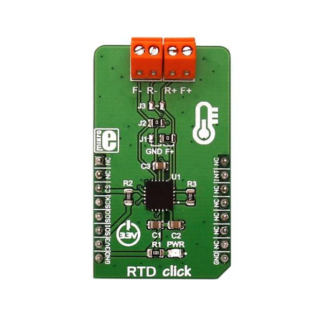
RTD click
PID: MIKROE-2815
Weight: 25 g
RTD click is based on MAX31865 resistance to digital converter from Maxim Integrated,
optimized for platinum resistance temperature detectors, or RTD. The click uses the PT100 type
platinum probe for temperature measurement. There are four screw terminals on the board, so
different PT100 probe types can be used with this design. This click board™ can work with 2, 3
or 4-wire PT100 probe types.
RTD probes are commonly used to measure a range of temperatures between −200°C and 500°C,
but the exact value depends on the specific probes used. Features like the 15bit ADC resolution,
input terminals overvoltage protection up to ±45V, fault detection, fast response time of 21mS and
the SPI interface, make the RTD click an ideal solution when it comes to precise measuring of
extremely high and low temperatures.
�
How the click works
RTD sensors are basically thermosensitive resistors – materials that change the resistance
depending on their temperature. In this case, the resistor is a small strip of platinum with a
resistance of 100Ω at 0°C - that is why it is called PT100. The RTD measurement is more stable
and precise than with most NTC/PTC thermistors, so it is commonly used for measuring
temperature in the laboratory and industrial processes.
Measurement probe is connected to the RTD click by using the screw terminals, and it has wires
that can be 1m long, which makes possible to measure high temperatures from a safe distance. To
successfully measure small differences in the sensor resistance, the signal must be amplified.
There is an input signal amplifier before the ADC converter, inside the MAX 31865 IC. Once
amplified, the signal goes through the ADC converter and then, this value can be then read
through the SPI interface on the mikroBUS™ socket. Since the temperature vs resistance curve
of the platinum probes is not ideal, a compensating calculation is done with the functions,
contained in the click library. The 15bit ADC can provide the resolution of ±0.3125°C, but the
total accuracy of the RTD click is ±0.5°C.
The RTD click can work with several different variations of the RTD probes:
The 2‐wire probe connection can give acceptable results when the RTD is located close to the
MAX31865. For the PT100 probes, the series resistance of 0.4Ω causes an error of approximately
1°C. Therefore, as the cable length increases, the error due to cable resistance can become
excessive.
The 3‐wire probe connection is a compromise that uses one less conductor than the 4‐wire
solution. If the cable resistances are well matched, the error due to cable resistance is canceled.
The 4‐wire probe connection eliminates errors due to cable resistance by using separate force
and sense leads.
To select proper mode for the type of the connected probe, the SMD jumpers on the click board
must be set to a proper position. The jumper settings can be found in the Onboard settings and
indicators table, below.
�
DRDY - Data ready pin is used to signal a ready status to the MCU. This pin will go to a LOW
logic state when there is a new conversion result is available in the data register. When a read
operation of an RTD resistance data register occurs, DRDY goes to a HIGH logic level. It can be
used to trigger an interrupt on the MCU so that the polling of the temperature registers can be
avoided.
Specifications
Type
Temperature
Applications
Measuring a wide range of temperatures in hard to reach places and in hazardous
conditions.
On‐board
modules
RTD click uses Maxim Integrated MAX31865 15bit resistance to digital converter,
optimized for platinum resistance temperature detectors (RTD)
RTD click can be equipped 2, 3 or 4‐wire PT100 RTD probe, measuring wide range of
Key Features temperatures with the accuracy of ±0.5°C, ±45V overvoltage protection, fast
measurement data processing of 21mS, DRDY pin for interrupt triggering...
Interface
GPIO,SPI
Input Voltage 3.3V
Click board
size
M (42.9 x 25.4 mm)
Pinout diagram
This table shows how the pinout on RTD click corresponds to the pinout on the mikroBUS™
socket (the latter shown in the two middle columns).
Notes
Pin
Pin
Notes
NC
1
AN
PWM
16
NC
NC
2
RST
INT
15
DRDY
CS
3
CS
RX
14
NC
SPI chip select
Data‐Ready output
�
SPI clock
SCK 4
SCK
TX
13
NC
SPI slave data out
MISO 5
MISO
SCL
12
NC
SPI slave data in
MOSI 6
MOSI
SDA
11
NC
Power supply
3.3V 7
3.3V
5V
10
NC
Ground
GND 8
GND
GND
9
GND
Ground
Onboard settings and indicators
Label Name
Power
LED
PWR
Default
J1
‐
Jumper
Description
Right
Power LED indicates that the click is powered on
For 3‐wire probe, connect to the RIGHT position. For 2 or 4‐wire probe,
connect to the LEFT position
J2
Jumper Soldered
Solder the 0Ω resistor when using the 2 or 3‐wire probe, leave open for 4‐
wire probe
J3
Jumper
Solder the 0Ω resistor when using the 2‐wire probe, leave open otherwise
NC
Note: RTD click is set to work with the 3-wire probe by default.
Software support
We provide a library for the RTD click on our LibStock page, as well as a demo application
(example), developed using MikroElektronika compilers. The demo can run on all the main
MikroElektronika development boards.
Library Description
This library contains functions for basic reading and writing of the click's registers, as well
as temperature conversion function that can convert raw data into degrees Celsius.
Key functions:
void rtd_writeRegister(uint8_t regAddress, uint8_t writeData) ‐ Writes data
into a register
uint16_t rtd_readTemperature() ‐ Reads temperature from temperature registers
float rtd_convertTemperature(uint16_t inputData, uint16_t
referentResistance) ‐ Converts raw data to degrees Celsius
�Examples Description
The application is composed of three sections:
System Initialization ‐ Initializes SPI peripheral, CS pin, and UART logger
Application Initialization ‐ Initializes RTD click driver, and sets the proper configuration mode
for 3‐wire RTD
Application Task (code snippet) ‐ Measures temperature, converts the data to Celsius
degrees, and outputs them via UART. The conversion function also accepts the value for the
resistance, which is used for the proper compensation, depending on the used referent
voltage resistor.
uint16_t readValue;
float convertedValue;
char testTxt [20];
readValue = rtd_readTemperature();
convertedValue = rtd_convertTemperature(readValue,
_RTD_REF_RESISTANCE_470);
floatToStr(convertedValue, testTxt);
mikrobus_logWrite("Current temperature: ", _LOG_TEXT
); mikrobus_logWrite(testTxt, _LOG_LINE );
delay_ms(1000);
The full application code, and ready to use projects can be found on our LibStock
page. Other mikroE Libraries used in this example:
UART
Conversions
C_string
Additional notes and information
Depending on the development board you are using, you may need USB UART click, USB
UART 2 click or RS232 click to connect to your PC, for development systems with no UART
to USB interface available on the board. The terminal available in all MikroElektronika
compilers, or any other terminal application of your choice, can be used to read the message.
https://www.mikroe.com/rtd‐click?utm_source=store%20banner&utm_campaign=rtd%20click 12‐5‐17
�