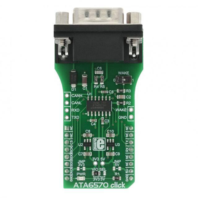
ATA6570 click
PID: MIKROE-2900
Weight: 33 g
ATA6570 click is an automotive diagnostic tool that allows CAN bus interfacing, in a series of
click boards™ aimed towards automotive diagnostics. The click carries the ATA6570, a highspeed CAN transceiver that interfaces a Controller Area Network (CAN) protocol controller and
the physical two-wire CAN bus. This IC has some unique features that make it a perfect choice
for any embedded CAN application.
It supports both CAN and CAN FD protocol types, partial networking, local and remote wake
up, an SPI interface for internal registers configuration, and it features six operating modes as
well as the undervoltage and overtemperature protection. The power consumption is taken to a
minimum, as the ATA6570 can power down the entire system until a valid wake-up frame is
received - even on a busy CAN bus. The car battery supply pin and the CAN bus pins are
protected from various interferences and voltage instabilities, typically observed in automotive
systems. ATA6570 click provides you with a robust and reliable CAN bus interface.
�How does it work?
ATA6570 click uses the ATA6570, a standalone high speed CAN transceiver IC from
Microchip, with the partial networking support. This IC supports both CAN and recently
established CAN FD protocols, up to 1Mbit/s and 5Mbit/s respectively. The communication
inside the CAN bus is differential and it is performed through the twisted pairs with the
characteristic impedance of 120Ω. The differential lines are driven by the CANH and CANL
drivers. This provides robustness and immunity to electromagnetic interferences, typically
observed in automotive systems. The ISO 11898 standard defines a single line of twisted-pair
cable as the network topology, terminated by the resistors with the characteristic impedance of
the CAN bus (120Ω) at both ends - in order to prevent signal reflection.
The dormant/recessive states are used for the message priority arbitration - the node which
transmits signal with the higher priority (the lower the binary message identifier number, the
higher the priority) will win the arbitration, and the node with the lower priority will abort the
transmission, waiting for the bus to become available again. Since the high logic level on the
CAN line is considered as the recessive, the TXD line has the internal pull-up resistor, making
the ATA6570 device stay in recessive mode if the pin is left afloat.
The ATA6570 device can be driven in the recessive or the dominant state with the TXD pin:
when the TXD pin is at the VCC level and the device works in Normal mode, the drivers at the
CANH and CANL pins are turned off. These pins are biased at 2.5 (VCC/2), with respect to the
GND, provided by the internal autonomous bus biasing circuitry and the device is in recessive
mode. Pulling the TXD pin to the GND will activate the CANH and CANL drivers and set the
bus to the dominant state. A TXD dominant timeout timer is started when the TXD pin is set to
low. If the low state on the TXD pin persists for longer than the predetermined time, the
transmitter will be disabled, releasing the bus lines to the recessive state. This function prevents
the hardware or software failure from driving the bus lines to a permanent dominant state,
blocking all network communications. When the device is in the Sleep or Unpowered mode, the
drivers will become highly resistive, rendering the device passive and completely ignored by the
CAN bus network.
�Although the RXD and TXD lines are interfaced with the microcontroller, the SPI bus is used to
set the internal registers, such as the partial networking registers and other status and
configuration related registers. The provided MikroElektronika library contains functions used to
easily set the parameters via the SPI bus, as well as to establish the communication with the
nodes.
Partial networking allows selective wake-up of ATA6570 click. Dedicated predefined frames can
wake up the device if it is configured to accept these frames. For this reason, when the device is
in the Standby or Sleep mode, it will still actively monitor the bus for those frames. The wake-up
CAN frame ID and data can be set by SPI. Besides waking up the device by the partial
networking feature, the device can also be woken up with the onboard switch connected to the
WAKE pin of the ATA6570 IC. Another wake-up source can be the SPI command, for those
modes where the SPI module is active, and the remote wake-up pattern on the CAN bus.
When in Sleep, Microcontroller Reset or Power Off mode, the INH pin which is routed to the
external regulators, will be turned off, reducing the power consumption of the external
elements.The #SHDN (shutdown) pins of the two LDO regulators, which are found on ATA6570
click, are connected to the INH pin. Both regulators take power from the car battery connector
(VS pin), providing 5V and 3.3V for custom needs. Outputs of those LDOs are routed via the
SMD jumpers that can be populated so that the LDOs can be used to power up the mikroBUS™
3,3V and 5V power rails. However, it should be noted that MikroElektronika does not advise
powering up own systems this way - that is why these jumpers are left unpopulated by default.
Overtemperature mode is activated when the temperature of the device becomes too high and the
device was previously working in Normal mode. The ATA6570 provides two levels of
overtemperature protection. When the first temperature level threshold is reached, an alarm in a
form of an interrupt on the RX pin (if set) and an appropriate status bit. If the temperature rises
even more, the device will shut down the CAN drivers.
Microcontroller Reset mode utilizes an integrated watchdog. When the watchdog event occurs, it
will trigger a pulse on the INH pin - this pin will be turned off for a predetermined period of
time, performing a power cycle reset on all devices connected via the ATA6570 click LDOs.
This is meant as a power cycle reset measure for a custom system, powered via the mikroBUS™
socket.
The onboard SMD jumper labeled as the VIO SEL is used to select which voltage rail of two
LDO regulators will be used as the logic voltage level (SPI, UART). It offers voltage selection
between 3.3V and 5V so that the click board™ can be interfaced with both the 3.3V and 5V
capable MCUs.
�Specifications
Type
CAN
Applications
ATA6570 click provides a robust and reliable CAN bus interface. This click is a perfect
choice for any embedded CAN application.
On-board
modules
ATA6570, standalone high speed CAN transceiver that interfaces a Controller Area
Network (CAN) protocol controller and the physical two wire CAN bus
The ATA6570 supports both CAN and CAN FD protocols, supports local and enhanced
Key Features remote wake up, and it has very low power consumption during Standby and Sleep
modes. CAN I/O pins are protected against conditions found in automotive applications.
Interface
SPI,UART
Input Voltage 3.3V or 5V
Click board
size
L (57.15 x 25.4 mm)
Pinout diagram
This table shows how the pinout on ATA6570 click corresponds to the pinout on the
mikroBUS™ socket (the latter shown in the two middle columns).
Notes
Pin
Pin
Notes
NC
1
AN
PWM
16
NC
NC
2
RST
INT
15
NC
SPI Chip Select
CS
3
CS
RX
14
TX
UART Transmit
SPI Clock
SCK
4
SCK
TX
13
RX
UART Receive
SPI Data Out
SDO
5
MISO
SCL
12
NC
SPI Data In
SDI
6
MOSI
SDA
11
NC
Power Supply
3V3
7
3.3V
5V
10
5V
Power Supply
Ground
GND
8
GND
GND
9
GND
Ground
�Note: The click is intended to be powered through the DE-9 connector, from the car battery. SMD
jumpers JMPR1 and JMPR2 should not be populated if the mikroBUS™ already provides power. These
jumpers should be populated only if powering up a custom board through the mikroBUS™ click, is
intended.
ATA6570 click electrical specifications
Description
Min
Maximum Differential Bus Voltage
Typ
-5
Thermal Shutdown Temperature
150
175
Max
Unit
18
V
190
°C
Additional pins
Name
I/O
Description
RXD
I
Additional RX pad
TXD
O
Additional TX pad
CANL
I/O
CAN L pad
CANH
I/O
CAN H pad
WAKE
I
Wake control
GND
-
Ground
Onboard settings and indicators
Label
Name
LD1 Power LED
JP1
VIO SEL
Default
Left
Description
Power LED indicator
Digital voltage level select
JMPR1 JMP 3V3 Unpopulated Connects 3.3V output to the mikroBUS™ socket
JMPR2
JMP 5V
Unpopulated Connects 5V output to the mikroBUS™ socket
�Software support
We provide a library for ATA6570 click on our LibStock page, as well as a demo application
(example), developed using MikroElektronika compilers and mikroSDK. The provided click
library is mikroSDK standard compliant. The demo application can run on all the main
MikroElektronika development boards.
Library Description
This library carries generic functions for registers writing and generic functions for
communication through CAN bus.
Key functions
void ata6570_writeReg( const uint8_t address, uint8_t input )- Writes register
uint8_t ata6570_readReg( const uint8_t address )- Reas register
void ata6570_writeByte(uint8_t input)- Sends single byte through CAN bus
uint8_t ata6570_readByte()- Reads byte received from CAN bus
uint8_t ata6570_byteReady()- Checks if new data has been received
Examples Description
The application is composed of three sections :
•
•
•
System Initialization - Initializes RST, CS, PWM pin as OUTPUT and INT, AN pin as INPUT and
UART module
Application Initialization - Driver initialization
Application Task - (code snippet) - Checks if new data byte has been received in RX buffer (ready
for reading), and if ready than reads one byte from the RX buffer. In second case application
task writes message data via UART.
void applicationTask()
{
// RECEIVER
#ifdef __RX__
if (ata6570_byteReady())
{
tmp = ata6570_readByte();
mikrobus_logWrite( &tmp, _LOG_BYTE );
}
�#endif
// TRANSMITER
#ifdef __TX__
uint8_t cnt;
for (cnt = 0; cnt < 9; cnt++)
{
ata6570_writeByte( MESSAGE_DATA[cnt] );
}
Delay_ms(2000);
#endif
}
The full application code, and ready to use projects can be found on our LibStock page.
MikroElektronika Libraries used in the example:
•
•
SPI
UART
Additional notes and information
Depending on the development board you are using, you may need USB UART click, USB
UART 2 click or RS232 click to connect to your PC, for development systems with no UART to
USB interface available on the board. The terminal available in all MikroElektronika compilers,
or any other terminal application of your choice, can be used to read the message.
mikroSDK
This click board is supported with mikroSDK - MikroElektronika Software Development Kit. To
ensure proper operation of mikroSDK compliant click board demo applications, mikroSDK
should be downloaded from the LibStock and installed for the compiler you are using.
For more information about mikroSDK, visit the official page.
Downloads
mikroBUS™ standard specifications
LibStock: mikroSDK
Libstock: ATA6570 click library
ATA6570 datasheet
ATA6570 click - 2D and 3D files
ATA6570 schematic
�https://www.mikroe.com/ata6570-click 2-5-18
�