RTC 7 CLICK
PID: MIKROE-2976
Weight: 20 g
RTC 7 Click is a real time clock module which has an extremely low power consumption, allowing it
to be used with a single button cell battery or a super capacitor, for an extended period of time. The
MAX31341B IC built on the RTC 7 click is able to output the time in the binary coded decimal (BCD)
format. Integrated, factory calibrated XTAL operating at 32.768 kHz ensures a very low time
deviation. However, the RTC 7 click has the onboard external, more precise crystal oscillator too. An
advanced interrupt feature allows many different uses such as alarm function, countdown timer
function, external event detection function, using an analog and the digital inputs and much more.
RTC 7 click is supported by a mikroSDK compliant library, which includes functions that simplify
software development. This Click board™ comes as a fully tested product, ready to be used on a
system equipped with the mikroBUS™ socket.
�Features such as the ability to be powered over the super capacitor, external event
capture pin, BCD time output format, and above all – an extremely low power
consumption, make RTC 7 click a perfect solution for the development of the IoT,
wearable and portable applications, logging devices, industrial and health-related time
metering applications, and all the other applications that require an accurate RTC for
their operation.
HOW DOES IT WORK?
RTC 7 click is based on the MAX31341B, a low-current Real-Time Clock with I2C
interface and power management from Maxim Integrated. Thanks to its high integration
level, this module provides high time accuracy, with a very low count of external
components required. It has a full RTC function, offering programmable counters,
alarms, and an interrupt engine with selectable event reporting sources. The small
dimension of the MAX31341B module itself, allow it to be used in very spaceconstrained applications, including wearables, medical equipment, and similar.
In addition to the MAX31341B, RTC 7 click is equipped with the 220mF super capacitor.
By utilizing an automatic backup switch, the IC is able to use an external battery power
source when there is no power supply on its main power terminals, thus allowing for
uninterrupted operation. Draining as low as 180nA of current, it can be operated with
the mentioned supercapacitor almost indefinitely. In addition, a trickle charge system
will replenish the super capacitor while the MAX31341B is powered over the main
power terminals (VDD, VSS). The voltage of the main power supply can range between
1.6V up to 3.6V.
The MAX31341B uses the I2C communication protocol for the communication with the
host MCU. Besides the I2C bus lines, two additional pins are also available on the
MAX31341B, INTA and INTB, allowing an interrupt to be reported to the host MCU, but
also to capture an external event and marking it with an automatic timestamp. The two
mentioned interrupt pins are routed to INT and AN pins of the mikroBUS™ socket,
�respectively. The user is able to set up standard clock and calendar functions (including
seconds, minutes, hours, weekdays, date, months, years with leap year correction), as
well as the interrupt functions for the periodic countdown timer, periodic time update,
alarm, external event, automatic backup switchover and power on reset (POR) events.
All these features are available when the module is operated over the backup power
supply (battery).
Besides other functions, RTC 7 click have one analog and one digitital external input,
labeled AIN and DIN. These universal inputs can be wired to any kind of external
trigger, which needs to trigger one of the interrupts. The digital input can be configured
to detect rising or falling edge, while the analog input, besides the edge detection,
supports the programmable threshold too. For detailed information on interrupts and
external triggers, refer to the MAX31341B datasheet.
The Click board™ is designed to work with 3.3V only. When using it with MCUs that use
5V levels for their communication, a proper level translation circuit should be used.
SPECIFICATIONS
Type
RTC
Applications
RTC 7 click is a perfect solution for the development of the IoT, wearable and
portable devices, logging devices, industrial and health-related time metering
applications, and all the other applications that require an accurate time-base
for various purposes
On-board
modules
RTC 7 click is based on the MAX31341B, a low-current Real-Time Clock with
I2C interface and power management from Maxim Integrated
Key Features
Ability to be powered over the super capacitor, external event capture pin,
BCD time output format, low power consumption, and more
Interface
GPIO,I2C
Click board
size
M (42.9 x 25.4 mm)
Input Voltage
3.3V
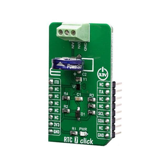
�PINOUT DIAGRAM
This table shows how the pinout on RTC 7 click corresponds to the pinout on the
mikroBUS™ socket (the latter shown in the two middle columns).
Notes
Pin
Pin
Notes
ITB
1
AN
PWM
16
NC
NC
2
RST
INT
15
ITA
NC
3
CS
RX
14
NC
NC
4
SCK
TX
13
NC
NC
5
MISO
SCL
12
SCL
I2C Clock
NC
6
MOSI
SDA
11
SDA
I2C Data
Power Supply
3.3V
7
3.3V
5V
10
NC
Ground
GND
8
GND
GND
9
GND
Interrupt B OUT
Interrupt A OUT
Ground
ONBOARD SETTINGS AND INDICATORS
Label
Name
Default
PWR
PWR
-
Description
Power LED Indicator
�SOFTWARE SUPPORT
We provide a library for the RTC 7 Click on our LibStock page, as well as a demo
application (example), developed using MikroElektronika compilers. The demo can run
on all the main MikroElektronika development boards.
Library Description
Library is used to get gmt time and local time by calculating data from data registers.
Library communicates with the device via I2C driver and driver functions. Library offers
a choice to get time data in two formats, 12 hours format and 24 hours format. For more
details check documentation.
Key functions:
uint8_t rtc7_writeReg( uint8_t register_address, uint8_t transfer_data ) - Function writes
one byte data to the register.
uint8_t rtc7_readReg( uint8_t register_address, uint8_t nBytes, uint8_t *dataOut ) -
Function reads the desired number of bytes from the register/s.
void rtc7_getGmtTime( rtc7_time_t *gmt_time ) - Function gets the gmt time data in both time
formats.
void rtc7_getLocalTime( rtc7_time_t *local_time ) - Function gets the local time data including
the determined time zone in calculations.
Examples description
The application is composed of three sections :
System Initialization - Initializes peripherals and pins.
Application Initialization - Initializes I2C driver and after the reset function configures the device to
works in 12 hours time format with desired input and output frequency. After that allows the timer
and the oscillator to be enabled.
Application Task - (code snippet) - Waits until device be stable and logs time after each second.
void applicationTask()
{
rtc7_getLocalTime( &timeDate );
if (checkYear == 0)
{
mikrobus_logWrite( "Wait...", _LOG_LINE );
while ((timeDate.year != timeSet.year) && (timeDate.year != (timeSet.year + 1)) && (ti
meDate.year != (timeSet.year ‐ 1)))
{
rtc7_getLocalTime( &timeDate );
� }
mikrobus_logWrite( "", _LOG_LINE );
checkYear = 1;
}
if (checkChange != timeDate.seconds)
{
rtc7_displayResults();
checkChange = timeDate.seconds;
}
}
Additional Functions :
void rtc7_displayResults() - Logs time results in the appropriate format on UART.
The full application code, and ready to use projects can be found on our LibStock page.
Other mikroE Libraries used in the example:
Conversions
I2C
UART
Additional notes and informations
Depending on the development board you are using, you may need USB UART
click, USB UART 2 click or RS232 click to connect to your PC, for development systems
with no UART to USB interface available on the board. The terminal available in all
MikroElektronika compilers, or any other terminal application of your choice, can be
used to read the message.
MIKROSDK
This Click board™ is supported with mikroSDK - MikroElektronika Software
Development Kit. To ensure proper operation of mikroSDK compliant Click board™
demo applications, mikroSDK should be downloaded from the LibStock and installed for
the compiler you are using.
For more information about mikroSDK, visit the official page.
�
https://www.mikroe.com/rtc‐7‐click/9‐10‐19
�