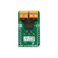
HALL CURRENT 5 CLICK
PID: MIKROE-3393 Weight: 29 g
Hall Current 5 Click is a very accurate electric current measurement Click board™ based on the
ACS733 IC. This IC is a galvanically isolated current sensor, which utilizes the Hall-effect principle.
Its most distinctive feature is its very low series resistance of only 1 mΩ, which makes this device a
nearly-perfect ammeter. The maximum current which can be measured with Hall current 5 click
ranges from -20 A to +20 A, with the optimized precision. By using the latest manufacturing
technologies, the ACS733 can be used on very high frequencies, making it a perfect solution for a
wide range of applications.
Hall current 5 Click is supported by a mikroSDK compliant library, which includes functions that
simplify software development. This Click board™ comes as a fully tested product, ready to be used
on a system equipped with the mikroBUS™ socket.
�The ACS733 has a precisely trimmed analog output, which changes linearly with the
applied current. Its excellent galvanic isolation simplifies the application, allowing the
Click board™ to be connected directly to the measured circuit. It can be used to
measure both DC and AC current. The ACS733 also features an overcurrent fault
detection, reporting this event on a dedicated pin. Hall Current 5 click can be used in
motor control applications, load detection and management applications, switch-mode
power supplies, overcurrent fault protection applications, and similar applications that
require accurate and reliable current sensing.
DO NOT TOUCH THE BOARD WHILE THE EXTERNAL POWER
SUPPLY IS ON!
Note: The Click board™ is to be used by trained personnel only, while applying high
voltages. A special care should be taken when working with hazardous voltage levels.
HOW DOES IT WORK?
Hall Current 5 utilizes the ACS733(KLATR‐AU), a Hall effect linear current sensor IC with
overcurrent fault detection, from Allegro Microsystems. This sensor utilizes the Hall
effect phenomenon to measure the current passing through the internally fused input
pins of the IC. This allows the series resistance to stay very low. Current through the
input rails of the IC generates a magnetic field, causing the Hall effect on the current
through the integrated sensor. These two current circuits are completely isolated, with
the basic isolation working voltage of about 600VRMS, allowing the Click board™ to be
used in high-side current sensing applications.
�The ACS733 senses current differentially, allowing higher precision and good rejection
ratio of common-mode interferences. The output voltage changes linearly with the
current in the primary circuit, with the ratio of 66mV/A, and it is available at the AN pin of
the mikroBUS™. Each IC is factory-calibrated, yielding a total output error as low as 1%
while operated in the temperature range from 25°C to 125°C, measuring 20A through
the primary conductor.
The FAULT pin indicates an overcurrent condition. If primary current exceeds the
specified range, this pin will be pulled to a LOW logic level. When the current through
the primary conductor drops below the overcurrent threshold, the FAULT pin will be
released. It is an open-drain output, which is pulled to a HIGH logic level by a resistor.
The overcurrent threshold level itself is programmable, and it is set by a voltage divider
to approximately 12.8A on Hall Current 5 click.
The FAULT pin has a very fast response of only 0.5 µs, allowing it to be used a part of
the overcurrent protection circuit. Naturally, it can be used as the interrupt pin, triggering
an interrupt request on a host MCU. For this reason, it is routed to the INT pin of the
mikroBUS™.
The secondary side of the ACS733 is powered from the 3.3V mikroBUS™ rail. As
explained already, currents flowing through the primary and secondary conductors are
galvanically isolated, protecting the voltage-sensitive parts of the circuit, as well as the
host MCU. The Click board™ should be connected in series with the load through which
the current is measured by using two connectors, labeled as IP+ and IP-. Both terminals
of a single terminal block are connected to the same conductor: one terminal block is
used for the positive current input, while the other terminal block is for the negative
current input. Having two connection terminals per input allows for better contact, thus
less resistance and higher current capacity. Very low internal resistance of only 1 mΩ of
the ACS733 itself will not disturb the current through the circuit, so the Click board™ will
not introduce its own error into the measurement. The voltage at the AN pin of the
mikroBUS™ can be sampled by an internal A/D converter of the host MCU, bearing in
mind that 66mV on this pin represents current of 1A through the primary conductor.
SPECIFICATIONS
Type
Current
Applications
It can be used in motor control applications, load detection and
management applications, switch-mode power supplies, overcurrent fault
protection applications, etc.
On-board
ACS733, a Hall effect linear current sensor with overcurrent fault detection,
�modules
from Allegro Microsystems.
Key Features
Very low series resistance, which makes this sensor an ideal ammeter, wide
current range, factory calibrated accuracy, low count of external
components, high isolation voltage.
Interface
Analog
Input Voltage
3.3V
Click board size
M (42.9 x 25.4 mm)
PINOUT DIAGRAM
This table shows how the pinout on Hall Current 5 Click corresponds to the pinout on
the mikroBUS™ socket (the latter shown in the two middle columns).
Notes
Pin
Pin
AN
1
AN
PWM
16
NC
NC
2
RST
INT
15
INT
NC
3
CS
RX
14
NC
NC
4
SCK
TX
13
NC
NC
5
MISO
SCL
12
NC
NC
6
MOSI
SDA
11
NC
Power Supply
3V3
7
3.3V
5V
10
NC
Ground
GND
8
GND
GND
9
GND
Analog OUT
Notes
Fault detection
Ground
�HALL CURRENT 5 CLICK MAXIMUM RATINGS
Description
Min
Typ
Max
Unit
Primary conductor resistance
-
1
-
mΩ
Minimum load Impedance
-
4
-
Ω
-20
-
+20
A
Fail detection current threshold
-
-
-12.8
A
Sensitivity
-
66
-
mV/A
Working voltage for basic isolation
-
-
616
V(RMS)
Measurement range with optimized accuracy
ONBOARD SETTINGS AND INDICATORS
Label
Name
Default
LD1
PWR
-
Description
PWR indication LED
SOFTWARE SUPPORT
We provide a library for the Hall Current 5 Click on our LibStock page, as well as a
demo application (example), developed using MikroElektronika compilers. The demo
can run on all the main MikroElektronika development boards.
Library Description
This library provides basic functionality for reading the current value and controlling the
click board.
Key functions:
float hallcurrent5_getCurrent(uint16_t adcValue) - Reads current in mA.
�
float hallcurrent5_getADCVoltage(uint16_t adcValue) - Reads voltage on the AN-pin.
void hallcurrent5_setADCResolution(float adcRes) - Set ADC resolution (10bit or 12bit).
Examples description
The application is composed of the three sections :
System Initialization - Sets AN pin and INT pin as INPUT.
Application Initialization - Initialization driver init and ADC Init.
Application Task - Reads current value in mA and this data logs to USBUART every 500ms.
void applicationTask()
{
int16_t ADC_value;
uint32_t sumADC = 0;
uint8_t cnt;
float current;
char demoText[ 50 ];
sumADC = 0;
for(cnt = 0; cnt