TEMP-LOG 5 CLICK
PID: MIKROE-3442
Weight: 23 g
Temp-Log 5 click is a temperature measuring Click board™ featuring the CAT34TS02,
an accurate temperature sensor IC with integrated Serial Presence Detect EEPROM.
Temperature Sensor measures and store temperatures at least 10 times in second.
Temperature measurement results can be retrieved by the host MCU via I2C interface,
and are compared to critical limits stored into internal registers. It also features
programmable event output function and supports three modes.
Temp-log 5 click is supported by a mikroSDK compliant library, which includes functions
that simplify software development. This Click board™ comes as a fully tested product,
ready to be used on a system equipped with the mikroBUS™ socket.
HOW DOES IT WORK?
The sensor IC used on the Temp-Log 5 click is CAT34TS02 from ON semiconductor that
combines a JC42.4 compliant Temperature Sensor (TS) with 2 Kb of Serial Presence
Detect (SPD) EEPROM. Temperature sensor measures and stores temperatures at
�least 10 times in second, allowing it to be retrieved by the host MCU via the I2C
interface. The result can be compared to critical limits, stored into internal registers. This
allows the sensor to reduce the processing workload of the host MCU by employing the
trigger limits mechanism: by asserting the EVENT line to a LOW logic level, the
CAT34TS02 is able to wake up the host MCU, reducing the power consumption. The
EVENT pin is routed to the INT pin of the mikroBUS™. The CAT34TS02 IC can be
configured to trigger an EVENT in three different modes: Interrupt mode, Comparator
mode, and Critical Temperature mode.
When set in the Interrupt Mode, the EVENT output will be asserted every time the
temperature crosses one of the alarm limits. Once the temperature exceeds the critical
limit, the EVENT remains asserted as long as the temperature stays above the critical
limit. The EVENT can be cleared by setting a bit in a corresponding register (must be
cleared by the software). However the pin will remain asserted as long as the
temperature exceeds the critical limits.
In the Comparator mode, the EVENT pin is asserted whenever the temperature is
outside the predefined limit values, and deasserted as soon as the temperature drops
under the limit (no need to clear the bit by the software). If set in the Critical
Temperature Mode, the EVENT pin will be asserted only if the temperature exceeds a
critical threshold limit. The limit values can be programmed via the corresponding
registers.
CAT34TS02 IC uses the I2C/SMBus protocols to communicate with the host MCU. Its
I2C bus pins are routed to the mikroBUS™ I2C pins and are pulled to a HIGH logic level
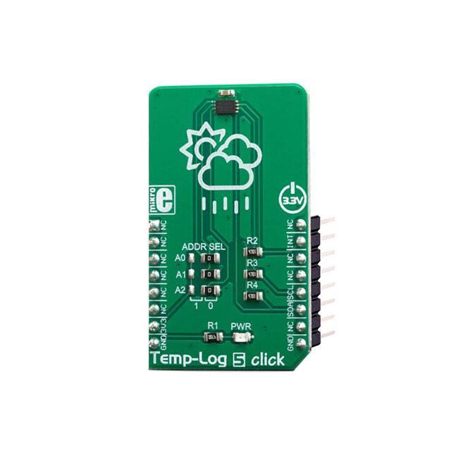
by the onboard resistors. The I2C slave address of the CAT34TS02 IC can be selected
by ADDR pins A0, A1 and A2: LOW logic level clears the corresponding address bit
(GND), while HIGH logic level sets the bit (VCC). This can be done using a group of
onboard jumpers, positioned under the label ADDR SEL.
�The provided click board™ library contains simple and easy to use functions, which
simplify configuring and reading of the measurement data. These functions are
demonstrated in the included example application and can be used as a reference for
custom projects. These functions can be used in mikroC, mikroBasic and mikroPascal
compilers for all MCU architectures, supported by MikroElektronika.
SPECIFICATIONS
Type
Temperature
Applications
Temp-Log 5 is a great solution for the development of various embedded
applications based on temperature measurement and data logging.
On-board
modules
CAT34TS02, a digital output temperature sensor with SPD EEPROM, by
ON semiconductor
Key Features
A very high measurement accuracy and repeatability, programmable
thresholds and hysteresis, a dedicated EVENT pin with a programmable
function, selectable resolution, 256 bytes of integrated EEPROM, and more
Interface
I2C
Input Voltage
3.3V
Click board
size
M (42.9 x 25.4 mm)
PINOUT DIAGRAM
This table shows how the pinout on Temp‐Log 5 click corresponds to the pinout on the
mikroBUS™ socket (the latter shown in the two middle columns).
Notes
Pin
NC
Pin
1
AN
PWM
16
NC
Notes
�NC
2
RST
INT
15
INT
NC
3
CS
RX
14
NC
NC
4
SCK
TX
13
NC
NC
5
MISO
SCL
12
SCL
I2C Clock
NC
6
MOSI
SDA
11
SDA
I2C Data
Power Supply
3.3V
7
3.3V
5V
10
NC
Ground
GND
8
GND
GND
9
GND
Interrupt output
Ground
TEMP-LOG 5 CLICK ELECTRICAL SPECIFICATIONS
Description
Min
Typ
Temperature Accuracy
-
+/-0.2
+/-0.4
°C
Temperature resolution
-
-
0.0625
°C
Operating temperature
-45
-
130
°C
Active range
-
-
±1.0
°C
Monitor range
-
-
±2.0
°C
Sensing range
-
-
±3.0
°C
10
-
400
kHz
I2C clock frequency
Max
Unit
�ONBOARD SETTINGS AND INDICATORS
Label
Name
Default
LD1
PWR
-
Description
PWR indication LED
SOFTWARE SUPPORT
We provide a library for the Temp‐Log 5 click on our LibStock page, as well as a demo
application (example), developed using MikroElektronika compilers. The demo can run
on all the main MikroElektronika development boards.
Library Description
The library initializes and defines the I2C bus driver and drivers that offer a choice for
writing data in TS register and read data form TS register. The library contains function
for reading Temperature data, functions for writing and reading EEPROM, functions for
reading Interrupt status and temperature status. The library provides full control of all
the registers that the modules contain.
Key functions:
float templog5_getTemperature() - Temperature Data
void templog5_writeEEPROM(uint8_t start_addr, uint8_t *dataIn, uint8_t nByte)- Write
EEPROM
void templog5_readEEPROM(uint8_t start_addr, uint8_t *dataOut, uint8_t nByte)- Read
EEPROM
Examples description
The application is composed of the three sections :
System Initialization - Initialization I2C module and set INT pin as INPUT.
Application Initialization - Initializes driver init, Test comunication, EEPROM write/read test and
configuration device for measurement.
Application Task - Reads Temperature data and logs data to the USBUART every 1 sec.
void applicationTask()
{
float Temperature;
Temperature = templog5_getTemperature();
FloatToStr(Temperature, demoText);
� mikrobus_logWrite("‐‐‐ Temperature: ", _LOG_TEXT);
mikrobus_logWrite(demoText, _LOG_LINE);
mikrobus_logWrite("‐‐‐‐‐‐‐‐‐‐‐‐‐‐‐‐‐‐‐‐‐‐‐‐", _LOG_LINE);
Delay_1sec();
}
The full application code, and ready to use projects can be found on our LibStock page.
Other mikroE Libraries used in the example:
I2C
UART
Conversions
Additional notes and informations
Depending on the development board you are using, you may need USB UART
click, USB UART 2 click or RS232 click to connect to your PC, for development systems
with no UART to USB interface available on the board. The terminal available in all
MikroElektronika compilers, or any other terminal application of your choice, can be
used to read the message.
MIKROSDK
This click board is supported with mikroSDK - MikroElektronika Software Development
Kit. To ensure proper operation of mikroSDK compliant click board demo applications,
mikroSDK should be downloaded from the LibStock and installed for the compiler you
are using.
For more information about mikroSDK, visit the official page.
�
https://www.mikroe.com/hall‐current‐6‐click//4‐9‐19
�