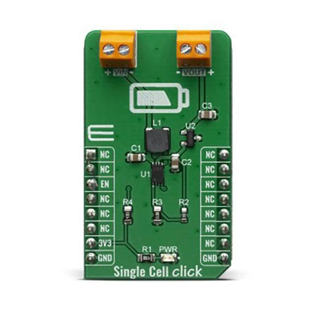
SINGLE CELL CLICK
PID: MIKROE-3844
Weight: 20 g
The Single Cell click is a Click board™ which features MCP16251 synchronous boost regulator with true
load disconnect and MCP1811A low-dropout (LDO) linear regulator that provide an ultra low quiescent
current during device operation of about 250nA and can be shut down for 5nA (typical) supply current
draw. Given the potential applications of these features, the Single Cell click can be used for one, two and
three-cell Alkaline and NiMH/NiCd portable products, solar cell applications, personal care and medical
products, smartphones, MP3 players, wireless sensors and many more.
The Single Cell click is supported by a mikroSDK compliant library, which includes functions that
simplify software development. This Click board™ comes as a fully tested product, ready to be used on a
system equipped with the mikroBUS™ socket.
�How does it work?
The Single Cell click is based around the MCP16251 from Microchip, a compact, highefficiency, fixed frequency, synchronous step-up DC-DC converter. This device provides an
easy-to-use power supply solution for applications powered by either one-cell, two-cell or threecell alkaline, NiCd, NiMH, one-cell Li-Ion or Li-Polymer batteries. Low-voltage technology
allows the regulator to start-up without high inrush current or output voltage overshoot from a
low-voltage input. High efficiency is accomplished by integrating the low-resistance N-Channel
boost switch and synchronous P-Channel switch. All compensation and protection circuitry are
integrated to minimize external components. MCP16251 is paired with MCP1811A device a
good choice for new ultra-long life LDO applications that have high-current demands, but
require ultra-low power consumption during sleep periods.
MCP16251 that's featured on Single Cell Click operates and consumes less than 14 µA from
battery after start-up, while operating at no load. The device provide a true disconnect from input
to output while in shutdown EN = LOW. While in shutdown it consume les than 0.6 µA from
battery.
The MCP1811A device is a 150 mA Low-Dropout (LDO) linear regulators that provide highcurrent and low-output voltages while maintaining an ultra-low 250 nA of quiescent current
during device operation. In addition, it can be shut down for 5 nA (typical) supply current draw.
The 150 mA output current capability, combined with the low output voltage capability, make
the MCP1811A a good choice for new ultra-long life LDO applications that have high-current
demands, but require ultra-low power consumption during sleep periods. The MCP1811A device
is stable with ceramic output capacitors that inherently provide lower output noise, and reduces
the size and cost of the entire regulator solution.
�The Single Cell click was designed to operate with a wide input voltage range after start-up,
down to 0.35V, to accommodate a large variety of input sources. When considering a primary
power solution for a design, the battery type and load current needs must be carefully selected.
The MCP16251 start-up voltage is typical 0.82V at 1 mA load but this does not act as an UVLO
start-up threshold. The device starts draining current to bias its internal circuitry before the 0.82V
input and cannot start-up or operate well with high-impedance sources because their voltage
varies in time, from zero to over 0.82V (i.e., energy harvesting). Start-up voltage is the point
where the device starts switching in closed loop and the output is regulated and depends on load
and temperature.
Batteries are available in a variety of sizes and chemistries and can support a variety of drain
rates. No matter the chemistry, most batteries have several things in common. They should not
be drained below their specified FEP (Functional End Point or Cut-Off Voltage). Below this
point, if the battery has a load applied to it, there will not be enough energy to deliver power
because all usable capacity is used. For an alkaline cell, FEP is 0.9V or 0.8V. Using the alkaline
cell below the FEP will increase the risk of leakage. There is an exception for alkaline batteries:
if the battery voltage is strictly monitored, it can be drained down to 0.5V in one-cell
applications only. For a rechargeable NiMH cell, the FEP value is usually 1.0V – 1.1V.
Another particular situation is powering a boost circuit from one rechargeable cell like NiMH or
NiCd. These applications need an external MCU to monitor the cell voltage or a separate UVLO
circuit to prevent deep discharging, which results in permanent cell damage. In a multi-cell
powered application (e.g., 2.4V typ. from two NiMH cells) deep discharging will result in a
reverse polarity charging of one of the cells due the unbalanced cell voltages, thus damaging the
respective cell.
Specifications
Type
Boost,Linear
Applications
Solar cell applications, personal care and medical products, smartphones, MP3
players, wireless sensors and many more
On‐board
modules
MCP16251 boost and the MCP1811A LDO
Key Features
High‐efficiency, Low‐voltage input
Interface
GPIO
Compatibility
mikroBUS
Input Voltage
3.3V
�Pinout diagram
This table shows how the pinout on Single Cell click corresponds to the pinout on the
mikroBUS™ socket (the latter shown in the two middle columns).
Notes
Pin
Pin
Notes
NC
1 AN
PWM
16
NC
NC
2 RST
INT
15
NC
Enable
EN
3 CS
RX
14
NC
NC
4 SCK
TX
13
NC
NC
5 MISO
SCL
12
NC
NC
6 MOSI
SDA
11
NC
Power Supply
3.3V
7 3.3V
5V
10
NC
Ground
GND
8 GND
GND
9
GND
Ground
Onboard settings and indicators
Label
Name
Default
Description
PWR LED GREEN
‐
Power LED Indicator
VIN ‐
‐
External Power Supply Input Connector
VOUT ‐
‐
Regulated Voltage Output Connector
Software Support
We provide a library for the Single Cell Click on our LibStock page, as well as a demo
application (example), developed using MikroElektronika compilers. The demo can run on all
the main MikroElektronika development boards.
�Library Description
The library covers all the necessary functions to control Single Cell Click board. The library
contains a function which enable or disable the regulator output switching.
Key functions:
void singlecell_enable() ‐ Enable the regulator output function.
void singlecell_disable() ‐ Disable the regulator output function.
Examples description
The application is composed of three sections :
System Initialization ‐ Initializes GPIO and LOG structures, set CS pin as output and start write
log.
Application Initialization ‐ Initialization driver enable's ‐ GPIO, also write log.
Application Task ‐ (code snippet) This is a example which demonstrates the use of Single Cell
board. This example shows the automatic control of the Single Cell click, waits for valid user
input and executes functions based on set of valid commands. Results are being sent to the
Usart Terminal where you can track their changes. All data logs on usb uart for aproximetly
every 1 sec when the data value changes.
Commands :'E' ‐ Enable regulator output; 'D' ‐ Disable regulator output;
void applicationTask()
{
char receivedData;
if ( UART_Rdy_Ptr() )
{
receivedData = UART_Rd_Ptr();
switch ( receivedData )
{
case 'E' :
{
singlecell_enable();
mikrobus_logWrite( " Enable regulator output ",
mikrobus_logWrite( "-------------------------",
break;
}
case 'D' :
{
singlecell_disable();
mikrobus_logWrite( " Disable regulator output",
mikrobus_logWrite( "-------------------------",
break;
}
}
}
}
_LOG_LINE );
_LOG_LINE );
_LOG_LINE );
_LOG_LINE );
�The full application code, and ready to use projects can be found on our LibStock page.
Other mikroE Libraries used in the example:
UART
Additional notes and informations
Depending on the development board you are using, you may need USB UART click, USB
UART 2 click or RS232 click to connect to your PC, for development systems with no UART to
USB interface available on the board. The terminal available in all MikroElektronika compilers,
or any other terminal application of your choice, can be used to read the message.
mikroSDK
This Click board™ is supported with mikroSDK - MikroElektronika Software Development Kit.
To ensure proper operation of mikroSDK compliant Click board™ demo applications,
mikroSDK should be downloaded from the LibStock and installed for the compiler you are
using.
For more information about mikroSDK, visit the official page.
https://www.mikroe.com/single‐cell‐click/11‐27‐19
�