CAN FD CLICK
PID: MIKROE-3933
Weight: 30 g
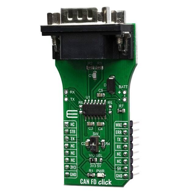
CAN FD Click is a add-on board based on TLE9252V CAN network transceiver,
designed for HS CAN networks up to 5 Mbit/s in automotive and industrial applications.
As an interface between the physical bus layer and the CAN protocol controller, the
TLE9252V drives the signals to the bus and protects the microcontroller against
interferences generated within the network. Given all the features its components offer,
the CAN FD Click is best used for for infotainment applications, cluster modules, radar
applications and HVAC.
CAN FD Click board™ is supported by a mikroSDK compliant library, which includes
functions that simplify software development. This Click board™ comes as a fully tested
product, ready to be used on a system equipped with the mikroBUS™ socket.
�HOW DOES IT WORK?
CAN FD Click features TLE9252V high speed CAN network transceiver from Infineon.
HS CAN is a serial bus system which connects microcontrollers, sensors and actuators
for real-time control applications. The TLE9252V supports both Bus Wake-up Pattern
(WUP) functionality and Local Wake-up, as well as CAN Flexible data rate transmission
up to 5Mbit/s. Additionally, the TLE9252V supports CAN Flexible data rate (CAN FD)
transmission up to 5 Mbit/s The TLE9252V also has an integrated over temperature
detection to protect the TLE9252V against thermal overstress of the transmitter.
The CAN FD Click supports five different Modes of operation. Each mode with specific
characteristics in terms of quiescent current, data transmission or failure diagnostic. For
the mode selection the digital input pins EN and STB are used.
Normal-operating mode - all functions of the TLE9252V are available and the device is fully
functional.
Receive-only mode - the transmitter is disabled and the receiver is enabled.
Stand-by Mode is a low power mode of the TLE9252V and the transmitter and the receiver are
disabled.
Sleep Mode - is a low power mode of the TLE9252V. In Sleep Mode the current consumption is
reduced to a minimum while the device is still able to detect a Wake-Up Pattern on WKE pin.
Go-to-Sleep command- is a transition mode allowing external circuitry like a microcontroller to
prepare the ECU to go to Sleep Mode.
The HS CAN transceiver TLE9252V includes a receiver and a transmitter unit, allowing
the transceiver to send data to the bus medium and monitors the data from the bus
medium at the same time by suing two wires. The TLE9252V converts the serial data
stream which is available on the transmit data input TxD, into a differential output signal
on the CAN bus, provided by the CANH and CANL pins.
�Given all the features its components offer, the CAN FD Click is best used for for
infotainment applications, cluster modules, radar applications and HVAC. The onboard
SMD jumper labeled as the VIO SEL is used to select which voltage rail will be used as
the logic voltage level. It offers voltage selection between 3.3V and 5V so that the click
board™ can be interfaced with both the 3.3V and 5V capable MCUs. The two UART
wires (RX and TX) can also be connected directly through two pins on the left edge of
the board. With R5 and R6 jumpers populated alows you to use click board with
standard 12V battery connected on battery pads at right side of board.
SPECIFICATIONS
Type
CAN
Applications
Infotainment applications, cluster modules, radar applications and
HVAC
On-board
modules
TLE9252V, a transceiver designed for HS CAN networks up to 5
Mbit/s in automotive and industrial applications from Infineon
Key Features
Fail safe features like TxD time-out, RxD Recessive Clamping and
Overtemperature shut-down, Very low electromagnetic emission
(EME), Dual Power Supply Solution or Undervoltage detection
Interface
GPIO,UART
Compatibility
mikroBUS
Click board
size
L (57.15 x 25.4 mm)
Input Voltage
3.3V or 5V
PINOUT DIAGRAM
This table shows how the pinout on CAN FD Click corresponds to the pinout on the
mikroBUS™ socket (the latter shown in the two middle columns).
�Notes
Pin
Pin
Notes
NC
1
AN
PWM
16
WKE
Wake up
Stand-by
STB
2
RST
INT
15
ERR
Error flag
Mode control
EN
3
CS
RX
14
TX
UART Transmit
EN
4
SCK
TX
13
RX
UART Receive
NC
5
MISO
SCL
12
NC
NC
6
MOSI
SDA
11
NC
Power Supply
3.3V
7
3.3V
5V
10
5V
Ground
GND
8
GND
GND
9
GND
Power supply
Ground
ONBOARD SETTINGS AND INDICATORS
Label
Name
Default
Description
PWR
LED GREEN
-
SW
SW
Down
VIO
SEL
-
Left
VIO voltage select
R5, R6
-
NP
Jumpers for battery usage
Power LED Indicator
Wake up switch sensitive on rising and falling
edge
�SOFTWARE SUPPORT
We provide a library for the CAN FD Click on our LibStock page, as well as a demo
application (example), developed using MikroElektronika compilers. The demo can run
on all the main MikroElektronika development boards.
Library Description
The library covers all the necessary functions to control CAN FD click board. Library
performs a standard UART communication.
Key functions:
canfd_byte_ready( ) - Write Single Byte
uint8_t canfd_read_byte( ) - Read Single Byte.
void canfd_set_operating_mode ( uint8_t op_mode ) - Set operating mode function.
Examples description
The application is composed of three sections :
System Initialization - Initializes UART, sets ERR ( INT ) pin as input and STB ( RST ) and EN ( CS )
pins as output, begins to write a log.
Application Initialization - Initialization driver enables - UART, performs an app mode, also write log.
Application Task - (code snippet) This is an example that demonstrates the use of the CAN FD click
board. This application task writes message data via UART. In the second case, checks if new data
byte have received in RX buffer ( ready for reading ), and if ready than reads one byte from RX
buffer. Results are being sent to the Usart Terminal where you can track their changes.
void application_task ( )
{
char tmp;
uint8_t drdy_flag;
if ( app_mode == APP_MODE_RECEIVER )
{
// RECEIVER ‐ UART polling
drdy_flag = canfd_byte_ready( );
if ( 1 == drdy_flag )
� {
tmp = canfd_read_byte( );
mikrobus_logWrite( &tmp, _LOG_BYTE );
}
}
else
{
// TRANSMITER ‐ TX each 2 sec
mikrobus_logWrite( " TX data: ", _LOG_TEXT );
Delay_ms( 1000 );
for ( tmp = 0; tmp
很抱歉,暂时无法提供与“MIKROE-3933”相匹配的价格&库存,您可以联系我们找货
免费人工找货- 国内价格
- 1+199.64367
- 5+195.65517