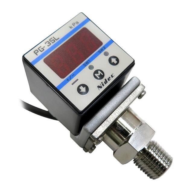
PG-35L
PRESSURE GAUGES
INTERNAL STRUCTURE (9/16-18UNF)
marking
7
6
Compatible with
EMC directive
4
5
2
3
1
Part name
Material
■ FEATURES
1
Fitting
O�For high vacuum pressure
O� For corrosive gases and liquids compatible with
SUS316L stainless steel diaphragm
O�Compact • Light weight • Drip-proof structure
(30 mm sq • 200 g • IP65)
O�Low consumption by nondisplay mode
O�Set data protection by panel lock function
2
Sensor module (oil less)
3
Sensor holder
4
Housing (Aluminum coating)
5
Adapter
6
Panel sheet
7
Shielded cable
SUS316L
PBT (UL-94-HB)
ADC 10, 12
Polyester (UL746)
Vinyl chlorid resin (UL2844)
■ MODEL NUMBER DESIGNATION
PG-35L-102R-NVC
Series name
Fitting
Pressure range
R2:R 1/4
G2:G 1/4
VC:9/16 - 18 UNF (Gusket joint)
102:− 100 ~ 100 kPa
103:− 100 ~ 1000 kPa
Pressure reference
Switch output interface
R:Compound pressure (Negative pressure ~ Positive pressure)
N:NPN 出力
P:PNP 出力
NPN open collector
PNP open collector
■ LIST OF MODEL NUMBERS
Gauge
Pressure reference
Fitting
Switch output
interface
Rated pressure
range
−100 ~ 100 kPa
R2
(R 1/4)
NPN
PG-35L-102R-NR2
PNP
A PG-35L-102R-PR2
G2
(G 1/4)
NPN
PG-35L-102R-NG2
PNP
A PG-35L-102R-PG2
VC
(9/16-18 UNF)
NPN
PG-35L-102R-NVC
PNP
A PG-35L-102R-PVC
−100 ~ 1000 kPa
PG-35L-103R-NR2
A PG-35L-103R-PR2
PG-35L-103R-NG2
A PG-35L-103R-PG2
PG-35L-103R-NVC
A PG-35L-103R-PVC
※ Verify the above model numbers when placing orders.
Marked A is manufactured upon receipt of order basis.
�PG-35L
PRESSURE GAUGES
■ STANDARD SPECIFICATIONS
O�Unless otherwise specified, the specs are defined at an ambient temperature of 25±5 °C and excitation voltage of 12 V DC.
Display
General specifications
Item
PG-35L
Model number
Pressure reference
Pressure medium
Rated pressure range
Maximum pressure
Break-down pressure
Operating temp. range
Compensated temp. range
Operating humidity
Protection grade
Type of mounting
Material of pressure port attachment
Net weight
Thermal error
Insulation resistance
Dielectric strength
Vacuum working pressure
Input voltage
Consumption current
Display element
Rated display range
Multiplier settings
Display cycle
Negative pressure display
Display accuracy
102R
kPa
kPa
kPa
°C
°C
%RH
g
kPa
Switch output
Output status
Analog output
103R
Gauge
SUS 316L Corrosive gases/liquids compatible with SUS 316L
− 100 ~ 100
− 100 ~ 1000
200
1500
300
2000
− 10 ~ 50
0 ~ 50
35 ~ 85(No condensation)
IP65
R 1/4, G 1/4, VC (9/16 - 18 UNF)
SUS 316L
Approx. 150(Including 2 m cable)
± 3 %F.S. (0 ~ 50 °C)
50 MΩ minimum
125 V DC 1 minute
1.4 × 10⁻⁴ Pa abs minimum
10.8 ~ 30 V DC(Including ripple percentage)
50 mA maximum
Full 3-digit LED
− 99.9 ~ 99.9
− 100 ~ 999
Max. 11 settings
Approx. 4 times/s
“–” LED is ON
±1%
NPN/PNP
2-point output (Transistor, Open collector output)
Separate mode / window comparator mode
30 V DC 100 mA maximum
1.2 V maximum (NPN), 2.2 V maximum (PNP)
Output mode
Switching capacity
Residual voltage
State indication
Switch hysteresis
Repeatability
Response
Output mode
Output 1 (Green LED), Output 2 (Red LED) Lighted when output is ON.
0 ~ 300 counts Adjustable
± 0.2 %F.S. ± 1 count
Approx. 5, 25, 250, 2500 ms adjustable
3 modes
Output voltage
V zero : Pin=0, V span : Pin=0 ∼ Pin (H)
1~5V
mode
( G/V
R mode
ZERO : 1 ± 0.2 V, SPAN : 4 ± 0.2 V
ZERO : 3 ± 0.2 V, SPAN : 2 ± 0.2 V
Impedance
Resolution
)
103 R (R mode) ZERO : 1.36 ± 0.2 V
SPAN : 3.64 ± 0.2 V
10 kΩ
1/204(Approx. 4.9mV/ Approx.0.123% F.S.)
■ ENVIRONMENTAL CHARACTERISTICS
Test item
Test conditions
Vibration
Shock
10 ~ 500 Hz, 98.1 m/s2 or 1.5 mm P-P, 3 directions for 2 hours each
Pressure cycling
Moisture resistance
EMC
490 m/s2, 3 directions for 3 times each
0 ~ Rated pressure、106 cycles
40 °C, 90 ~ 95 %RH, 240 hrs.
EMI : EN55011: 2007, A2 : 2007 Group 1, class Bý
EMS : EN61326-1: 2006 Table 2
※1 Change in the pressure indication, switch operating points and analog output.
Permissible change
[
※1
± 2 %F.S. maximum after test
Amount of analog output fluctuation is permitted
by adding conversion error of 20 mV.
]
※1
Pressure indication, switch operating pressure and analog output�: ± 5 %F.S. maximum during test
�PG-35L
PRESSURE GAUGES
■ INTERNAL ELECTRICAL SCHEMATICS
O�NPN
O�PNP
1
2
1
LED Indicator
2
LED Indicator
Power B
Load
Pressure
Power B
A.Output
S.Output1
Load
Pressure
S.Output1
S.Output2
Main circuit
Sensor
S.Output2
Main circuit
Sensor
Load
A.Output
Load
Common
Common
LED
LED
Pressure indication
Pressure indication
Shield
Shield
■ SELECTION OF DISPLAY MULTIPLIER
The last digit/letter represents the selection code : Blinking red LED indicates negative pressure.
(− Pr ∼+ Pr)Pressure range
102R
103R
– 99.9 ~ 99.9
– 100 ~ 999
– 1.02 ~ 9.99
– 999 ~ 999
– 750 ~ 750
Display multiplier
×1
× 0.0102
× 10.2
× 7.501
× 102
× 0.01
× 10
× 0.145
× 0.000145
× 0.001
× 0.2953
Selection code
1
2
3
4
5
6
7
8
9
A
b
– 1.00 ~ 9.99
– 999 ~ 999
– 14.5 ~ 14.5
– 14 ~ 145
– 29.5 ~ 29.5
– 0.10 ~ 1.00
– 29 ~ 29.5
Diagonal column: Display multiplier cannot be
selected due to resolution and number of digits.
(Selection code is not indicated either.)
Selection code is set at “A” prior to shipment.
■ ANALOG OUTPUT MODE
Pressure range
−Pr
0
Pr
1V
5V
Display
1
R モード R mode
2
G モード G mode
1V
5V
Selection code is set at “G” prior to shipment.
■ SWITCH OUTPUT MODE
SW1
Output
Mode
Operation
Separate
HI
LO
Separate mode
SW2
Window comparator
A
B
Separate
HI
LO
(HI operation)
Window comparator
A
B
Pressure setting
(Operating point)
(A operation)
ON
OFF
ON
ON
OFF
P1: SW1
P2: SW2
H
H
P1
Pr
-Pr
S- 1
S- 2
S- 3
S- 4
C- 5
C- 6
C- 7
C- 8
Window comparator mode
P2
-Pr
Pr
H
(LO operation)
H
(B operation)
ON
ON
P1: SW1
P2: SW2
-Pr
OFF
Pr
H
H
P1≦P2 or P1≧P2
Setting 1
(Lower limit) : Setting 1
(Upper limit) : Setting 2
Setting 2
(Lower limit) : Setting 1
(Upper limit) : Setting 2
Note 1. In the Separate Mode, setting 1 corresponds to SW1, and
Setting 2 corresponds to SW2.
Note 2. In the Window Comparator Mode, the minimum value for
SW1 and SW2 corresponds to Setting 1 and the maximum
value corresponds to Setting 2.
H:Switch hysteresis、
P1=Setting 1、P2=Setting 2
OFF
P1
P2
-Pr
OFF
Pr
H
H
P1≦P2–2H
�PG-35L
PRESSURE GAUGES
■ OUTLINE DIMENSIONS
Unless otherwise specified tolerance : ± 0.5 (Unit: mm)
O�Fitting R2 (R 1/4)
31.4
Panel sheet :
Polyester
30
15
37
21
Wire color
Brown
Gray
Black
White
Blue
Shield
10.5
( φ 4)
5-core shielded cable
8.5
8
Vent hole
8
5
Adapter : ADC10, 12
Sensor holder : SUS316L
R1/4 (PT 1/4)
SUS316L
(With M5 female screw)
(21)
21
6.5
10
Housing : PBT
(39.5)
(68.7)
15
10
L = 2000 ± 100
AWG26 UL No.2844
Connection
Power B
Analog output
Switch output 1
Switch output 2
Common
Fitting
2 – M4
Depth 5
16
7.7
16
Pressure port M5
O�Fitting G2 (G 1/4)
31.4
30
Panel sheet :
Polyester
15
37
21
10.5
( φ 4)
5-core shielded cable
8.5
8
Vent hole
Adapter : ADC10, 12
8
10
5
Housing : PBT
(40.5)
(68.2)
6.5
21
15
10
L = 2000 ± 100
AWG26 UL No.2844
2 – M4
Depth 5
Sensor holder : SUS316L
G1/4 (PF 1/4)
SUS316L
(With M5 female screw)
(21)
16
7.7
16
Pressure port M5
O�Fitting VC (9/16 - 18 UNF)
31.4
37
Panel sheet : Polyester
Vent hole
10.5
8
15
8.5
( φ 4)
5-core shielded cable
L = 2000 ± 100
AWG26 UL No.2844
21
6.5
5
Housing : PBT
10
(39.5)
(71.2)
15
10
21
8
30
Adapter : ADC10, 12
9/16–18UNF
SUS316L
2 – M4
Depth 5
Sensor holder : SUS316L
(21)
16
7.7
16
※ Accessories (sold separately) are available for common use with PG-30, PG-35, PG-75 series. (P.175)
�
很抱歉,暂时无法提供与“PG-35L-102R-NR2”相匹配的价格&库存,您可以联系我们找货
免费人工找货- 国内价格 香港价格
- 1+4501.132811+582.62473
- 5+4245.012595+549.47264
- 10+4149.4297810+537.10044