RayVio LED Driver
July 17, 2017
Proprietary and confidential
�Safety Guidelines
Eye and Skin Safety Guidelines
1. Use appropriate eye and skin protection
when operating UV-C LEDs.
2. Do not directly look at the LED when it
is powered on.
3. To avoid the risk of eye damage use
caution when examining UV-C LEDs
with optical instruments.
Proprietary and confidential
2
�RayVio LED Driver - Description
• Power supply – Driver IC TPS61165
• Battery
– The driver IC boosts input voltage up to LED operating voltage
»
Example: Li-Po battery – 3.7V, 300 mAh
• Micro USB
– Used to charge the battery from phone charger, computer and etc.
– The driver can also operate without battery when USB is connected
• External power supply
– Battery connector can be used to connect an external power supply
»
Example, 30W Universal AC/DC Adapter with 3V to 12V Selectable Output
– Make sure Vin is equal to or less than Vout
»
»
Vin: min. 3V – max. 18 V
Vout: min. Vin – max. 38 V
• Output current is user controllable
• Presets: 50 mA, 150 mA or 200 mA
• Plus a user configurable option by selecting appropriate resistor value
– Output Current = 200 mV/resistor value
»
i.e. use a 2.49 ohm resistor for R5 to obtain 80 mA output current.
• LED On/Off control
• Presets: on-board On/Off push button or
• A user supplied external control signal
Proprietary and confidential
3
�LED Driver Schematic
Proprietary and confidential
4
�LED Driver Layout
•
•
•
30 mm x 30 mm board size
Two-layer PCB board
Four 3 mm diameter mounting
holes on the corners
Proprietary and confidential
5
�LED Driver BOM
RayVio Corp.
Project
Date
RayVio LED Driver revD
5/2/2017
Part
C1
C2
C3
C4
C5
D1
J1
J2
J3
J4
J5
J6
J7
L1
LED1
LED2
R1
R2
R3
R4
R5
R7
R8
R9
SW1
U1
U2
Value
4.7uF
1uF
220nF
4.7uF
4.7uF
60V
Device
CAP0603
CAP0603
CAP0603
CAP0603
CAP0603
Diode Schottky
ED2740-ND
455-2247-ND
M04X2
M03PTH
M02PTH
USB_MICROB_PLUGRA-LI
M02PTH
15uH
INDUCTORCR54
Red
LEDCHIP-LED0805
Green
LEDCHIP-LED0805
100k
RESISTOR0805-RES
4.02, 1%
RESISTOR0805-RES
1.33, 1%
RESISTOR0805-RES
1.0, 1%
RESISTOR0805-RES
DNP
RESISTOR0805-RES
470 RESISTOR0805-RES
2k
RESISTOR0805-RES
240 RESISTOR0805-RES
PUSHBUTTON-D PUSHBUTTON-DPST
TPS61165SOTTPS61165DBVR
MCP73831
MCP73831T-2ACI/OT
Proprietary and confidential
Package
0603
0603
0603
0603
0603
SMA
BULK
BULK
2X4
1X03
1X02
USB-MICROB-RA
1X02
CR54
0805
0805
0805
0805
0805
0805
0805
0805
0805
0805
BULK
SOT23-6
SOT23-5
Digikey Part #
445-9042-1-ND
445-11263-1-ND
445-7408-1-ND
445-9042-1-ND
445-9042-1-ND
RB060M-60TR-ND
ED2740-ND
455-2247-ND
952-2123-ND
952-2264-ND
952-2262-ND
609-4618-2-ND
952-2262-ND
587-2366-2-ND
HT17-2102SURC
HQ17-2102SYGC
311-100KCRTR-ND
541-4.02CCCT-ND
541-1.33CCCT-ND
541-1.00CCTR-ND
Description
CAP CER 4.7UF 35V X5R 0603
CAP CER 1UF 50V JB 0603
CAP CER 0.22UF 50V X7R 0603
CAP CER 4.7UF 35V X5R 0603
CAP CER 4.7UF 35V X5R 0603
Diode Schottky 60V 2A Surface Mount PMDU
2 Position Wire to Board Terminal Block Horizontal with Board 0.138" (3.50mm) Through Hole
2 Positions Header, Shrouded Connector 0.098" (2.50mm) Through Hole Tin
8 Positions Header, Unshrouded, Breakaway Connector 0.100" (2.54mm) Through Hole Tin
3 Positions Header, Unshrouded, Breakaway Connector 0.100" (2.54mm) Through Hole Tin
2 Positions Header, Unshrouded, Breakaway Connector 0.100" (2.54mm) Through Hole Tin
CONN USB MICRO B RECPT SMT R/A
2 Positions Header, Unshrouded, Breakaway Connector 0.100" (2.54mm) Through Hole Tin
15µH Shielded Wirewound Inductor 1.8A 104 mOhm Max Nonstandard
Red 638nm LED Indication - Discrete 1.8V 0805 (2012 Metric)
Green 569nm LED Indication - Discrete 2.1V 0805 (2012 Metric)
RES SMD 100K OHM 1% 1/8W 0805
RES SMD 4.02 OHM 1% 1/8W 0805
RES SMD 1.33 OHM 1% 1/8W 0805
RES SMD 1 OHM 1% 1/8W 0805
Custom Define
311-470ARTR-ND
RES SMD 470 OHM 5% 1/8W 0805
311-2.00KCRTR-ND
RES SMD 2K OHM 5% 1/10W 0603
311-240ARTR-ND
RES SMD 240 OHM 5% 1/8W 0805
CW179-ND
Pushbutton Switch DPDT Standard Through Hole
296-27597-2-ND
LED Driver IC 1 Output DC DC Regulator Step-Up (Boost) PWM Dimming 1.2A (Switch) SOT-23-6
MCP73831T-2ACI/OTCT-ND Charger IC Lithium-Ion/Polymer SOT-23-5
6
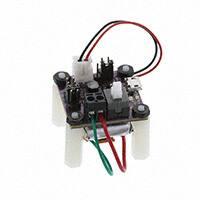
�Assembled LED Driver
Connector to
battery or external
power supply
• PCB operation with
RayVio LEDs is
discussed in slide 913
Headers for external
On/Off control
USB
Charging
Port
Use a jumper cap to
select current
50 mA
150 mA
200 mA
Custom
R5, reserved for
custom current
UV-C LED
Connector
Proprietary and confidential
On/Off
Button
Short pins with
jumper cap for
battery
operation
7
�How to Use Push Button and External On/Off Control
•
•
Use push button for on/off control
(default config.)
–
Use external on/off control (e.g.
control signal from Arduino)
–
–
Use jumper cap to short pin 2 and pin 3
on header labelled “J4”.
–
Push down the built-on-board on/off button.
Use jumper cap to short pin 1 and pin 2 on
header labelled “J4”;
Connect “J5” to control signal
•
•
J5: pin 1
J4
pin 1
Proprietary and confidential
2
Pin 1 for “+”
Pin 2 for “-” or “GND”
2
3
8
�User Instruction
for Driving Single XE or XP1 LED
Proprietary and confidential
9
�Single XE or XP1 LED
•
Note: pin 1 and pin 2 of J7 must be shorted (e.g. with a
jumper cap) for battery operation and must be
disconnected when using an external power supply in
order to protect the charging IC.
J7
•
Power Supply
–
Option 1 – Battery
•
•
•
•
•
–
Option 2 – Micro USB
•
•
–
For example, Li-Po battery – 3.7V, 300 mAh
The driver IC boosts 3.7 V input voltage up to LED operating voltage.
Use standard micro USB cable to charge the battery from computer or
phone charger.
During charging, red indicator light is on. Green will be on once battery is
fully charged.
Note: driver board can only charge a single cell Li-Po battery (3.7
V). Dual cell Li-Po batteries cannot be charged thus should not be used.
With no battery, the driver can also operate when the USB is connected.
Use proper USB power adapter. For example, common USB charging
adapters are rated 5 V, 2 A output.
Option 3 – External Power Supply
•
Connect external power supply to power input port, J2.
–
•
For example, 30W Universal AC/DC Adapter with 3V to 12V Selectable Output.
Limit max. supply voltage to 5 V for single XE or XP1 operation.
Proprietary and confidential
10
�Battery Life Example
• An XE LED driven at 80 mA.
– Using a fully charged 900 mAh
battery.
• Data shows the relative LED
output over time.
– 6 hours of continuous use.
Proprietary and confidential
11
�User Instruction
for Driving a Single XP4 LED
(Must Use an External Power Supply)
Proprietary and confidential
12
�Single XP4 LED (Use External Power Supply)
•
•
Note: pin 1 and pin 2 of J7 must be disconnected for external power
supply in order to protect the charging IC.
Connect external power supply to power input port, J2.
–
•
For example, 30W Universal AC/DC Adapter with 3V to 12V Selectable Output.
Data in the table below is based on driving a single RayVio XP4 LED with an
external power supply at room temperature.
–
Actual measurements may vary as result of component variation (i.e. values of precision
resistors)
Supply Voltage
(V)
9
10
11
12
Proprietary and confidential
Preset LED Current Measured LED Current
(mA)
(mA)
50
50.3
150
143.7
200
192.7
50
50.1
150
138.8
200
192.1
50
50.2
150
135.2
200
185.6
50
50.2
150
133.8
200
180.9
13
�Confidential and Proprietary
14
�
很抱歉,暂时无法提供与“RVDB-PCB-KT”相匹配的价格&库存,您可以联系我们找货
免费人工找货