DR67 SERIES | 25/30 AMPS
DIN RAIL MOUNT SOLID STATE RELAYS
Introduction
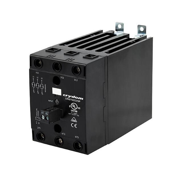
The DR67 is a compact 3-phase solid state relay in a DIN rail 67.5mm wide package with output ratings up to 30 Amps per channel @ 40°C. Its built-in
overvoltage protection and the optional overtemperature protection make it suitable for demanding heating, motion and lighting applications.
It’s easy to install and its large cage clamp terminals allow connecting wires up to 2 AWG size on the output terminals without the use of any additional
accessories, therefore reducing installation cost and time.
UL listed and VDE certified, the DR67 is a powerful and versatile solid state relay with superior performance when compared to previous generations and
competitor products.
Features
• 3-Phase AC Output DIN Rail Mount SSRs
• Output ratings up to 30 Amps at 600 VAC
• 2 & 3 controlled Legs option
• Over Temperature protection w/alarm (optional)
• Built-in overvoltage protection
• IP20 touch-safe housing
• AC or DC control
• cULus listed and VDE approved
Applications
• Plastic injection molding equipment
• Packaging equipment
• Industrial ovens
• Lighting control
• Professional cooking equipment
• Pump control
• Conveyor drives
• HVAC&R
PRODUCT SELECTION
Control Voltage
25A
30A
4-32 VDC
DR6760D25P
DR6760D30P
90-280 VAC/VDC
DR6760A25P
DR6760A30P
Page 1
Copyright © 2019 Sensata Technologies, Inc.
www.sensata.com
�Example : DR6760A25RPTA
ORDERING OPTIONS
Description of part number example
DR67
Family
60
x
xx
P
x
xx
Operating Voltage
48-600 VAC
Control Voltage
D = 4-32 VDC (4-28 VDC for TA option)
A = 90-280 VAC/VDC
Rated Load Current
25 = 25A, 3-legs
30 = 30A, 2-legs
Switching Type
Blank = Zero voltage turn on
R = Instantaneous turn on
Overvoltage Protection
P = With internal overvoltage protection
Over Temperature Protection(1)
Required for valid part number
For options only and not required for valid part
number
Blank = No Over Temperature protection
TA = With Over Temperature Protection and Alarm Output
SPECIFICATIONS
Output (2)
Description
25A
30A
48-600
48-600
1200
1200
1
1
Minimum Off-State dV/dt @ Maximum Rated Voltage [V/
μsec]
500
500
Load Current, General Use UL508/LC A IEC62314 @ 40°C
[ARMS]
25
30
Load Current, Motor Starting UL508 FLA/LC B IEC62314 @
40°C [ARMS]
12/6.8
12/6.8
100
100
716/750
716/750
1.15
1.20
2563/2343
2563/2343
0.5
0.5
Motor Rating UL 508: 120 VAC / 240 VAC / 480 VAC [HP]
1.5/3.0/7.5
1.5/3.0/7.5
Motor Rating IEC62314: 240 VAC / 400 VAC / 500 VAC [kW]
1.5/3.0/4.0
1.5/3.0/4.0
Operating Voltage (47-440Hz) [VRMS]
Transient Overvoltage [Vpk]
(3)
Maximum Off-State Leakage Current @ Rated Voltage
[mARMS]
Minimum Load Current [mARMS]
Maximum 1 Cycle Surge Current (50/60Hz) [Apk]
Maximum On-State Voltage Drop @ Rated Current [VRMS]
Maximum 1/2 Cycle I² t for Fusing (50/60Hz) [A² sec]
Minimum Power Factor (at Maximum Load)
Page 2
Copyright © 2019 Sensata Technologies, Inc.
www.sensata.com
�Input (1)
Description
DR6760Dxxx
DR6760Axxx
wo-TA Option
w-TA Option
4-32 VDC (4)
4-28 VDC(4)
Control Voltage Range
wo-TA Option
w-TA Option
90-280 VAC/VDC
Maximum Reverse Voltage
-32 VDC
-
Minimum Turn-On Voltage
4 VDC
90 VAC/VDC
Must Turn-Off Voltage
1 VDC
5 VAC/VDC
Minimum Input Current (for on-state)
25 mA
20 mA
1 mA
1 mA
Maximum Input Current
40 mA
50 mA
4 mA
8 mA
Nominal Input Impedance
Current Limited
Maximum Turn-On Time [msec]
1/2 Cycle
Maximum Turn-Off Time [msec]
(5)
Switching mode
10
1/2 Cycle
20
Description
DR6760Dxxx
DR6760Axxx
Output type
Solid State
Solid State
60 VDC
400 VDC / 265 VAC
60
60
Alarm (2)
Maximum Output Voltage
Maximum Alarm Output Current [mA]
General (2)
Description
Parameters
Dielectric Strength, Input to Output (50/60Hz)
4k VRMS
Dielectric Strength, Input/Output to Case (50/60Hz)
4k VRMS
Minimum Insulation Resistance (@ 500 VDC)
109 Ohms
Maximum Capacitance, Input/Output
25 pF
Ambient Operating Temperature Range
-40 to 80 °C
Ambient Storage Temperature Range
-40 to 100 °C
Short Circuit Current Rating (6)
100 kA
Weight (typical)
31 oz (880 g)
Housing Material
UL94 V-0
Heat Sink Material
Aluminum
DIN Rail Clip Material
Zinc Plated Steel
Hardware Finish
Nickel Plating
Input Terminal Screw Torque Range (lb-in/Nm)
5/0.5
Load Terminal Screw Torque Range (lb-in/Nm)
18-20/2.0-2.2
Humidity per IEC 60068-2-78 (7)
93%
LED Input Status Indicator
See status chart
Overvoltage Category
III
Impulse Withstand Voltage According to IEC 60664-1
6 kV
Page 3
Copyright © 2019 Sensata Technologies, Inc.
www.sensata.com
�EQUIVALENT CIRCUIT BLOCK DIAGRAMS/WIRING DIAGRAMS
DR6760X25
DR6760X30
L1
L2
L3
48-600 VAC, 47-440 Hz
L1
L2
L3
Short circuit and overload
current protection
/>
/>
/>
3/L2
1/L1
L2
L3
T1
T2
T3
5/L3
48-600VAC
L1
INPUT
A2 -
A1+
INPUT CTRL
4-32VDC
CONTROL
INPUT
4/T2
2/T1
Motor Controller
Application
T1
T2
T1
T2
6/T3
General Use
Application
T3
T1
T3
T2
T3
M
3
DR6760X30
( 2 CONTROLLED LEGS )
DR6760X25
( 3 CONTROLLED LEGS )
MAIN CIRCUIT
MAIN CIRCUIT
L1
L2
L3
+A1
L1
L2
L3
+A1
T1
T2
T3
-A2
T1
T2
T3
-A2
Copyright © 2019 Sensata Technologies, Inc.
www.sensata.com
Page 4
�L1
L2
L3
DR6760X25TA
DR6760X30TA
48-600 VAC, 47-440 Hz
L1
L2
L3
Short circuit and overload
current protection
/>
/>
/>
3/L2
1/L1
L2
L3
T1
T2
T3
5/L3
48-600VAC
L1
INPUT
Motor Controller
Application
T1
T2
A3
CONTROL
INPUT
A4
A2 -
A1+
ALARM
OUTPUT
A2
INPUT CTRL
4-32VDC
A1
4/T2
2/T1
T1
T2
6/T3
General Use
Application
T3
T1
T3
T2
T3
M
3
DR6760X25TA
(3 CONTROLLED LEGS )
DR6760X30TA
(2 CONTROLLED LEGS )
ALARM
OUTPUT
MAIN CIRCUIT
ALARM
OUTPUT
MAIN CIRCUIT
L1
L2
L3
+A1
A3
L1
L2
L3
+A1
A3
T1
T2
T3
-A2
A4
T1
T2
T3
-A2
A4
Page 5
Copyright © 2019 Sensata Technologies, Inc.
www.sensata.com
�MECHANICAL SPECIFICATIONS
Tolerances: ±0.02 in / 0.5 mm
All dimensions are in inches [mm]
3X Ø .17
4.4
MOUNTING HOLE
2.66
67.5
1.11
28.2
4X
.87
22.2
3/L2
1/L1
T2
T3
48-600VAC
T1
5/L3
4.04
102.6
INPUT
INPUT CTRL
4-32VDC
2.93
74.5
L3
A2 -
3.61
91.8
L2
A1+
4.39
111.5
L1
4/T2
2/T1
6/T3
1.96
49.7
5.82
147.8
1.45
36.8
5.12
130.1
2.31
58.6
Page 6
Copyright © 2019 Sensata Technologies, Inc.
www.sensata.com
�SURGE CURRENT INFORMATION(8)
25A & 30A
THERMAL DERATE INFORMATION
STATUS CHART
(only for models with overtemperature protection)
TA SUFFIX MODELS
Conditions
1,11
Description
Initial Condition.
Control Input is On, Output is activated,
2, 4
temperature rises, Green LED is On.
3, 7
Control Input is Off, Output is Off.
5
LED changes to solid Orange color.
Output is Off due to overtemperature,
6, 9
Alarm is latched On, LED changes to
solid red.
While Control Input is Off: Output,
7
Alarm and LED remains Off. (Control
Input Min. 100ms Off to reset values)
Control Input is On, Output is on and
8
temperature rises.
Alarm will reset until Control Input
6, 10
is Off.
* Max. 60 ms OFF when applying PWM on Control Input.
Green
LED
Color
Red
Yellow
Output On
Alarm
Pre-Alarm
Page 7
Copyright © 2019 Sensata Technologies, Inc.
www.sensata.com
�INSTALLATION INSTRUCTIONS
Mounting on DIN Rail
• Locate rail and align with non moveable end of DR67 DIN clip.
• Using reasonable force, push DR67 in the direction of the arrow (as shown in fig.1).
• For removal pull release tag by moving blade of screwdriver in direction of arrow and pull it away from DIN rail.
Mounting on Panel
• Locate the panel section on which the DR67 SSR will be mounted on (as shown in fig.2)
• DIN clip includes tabs for this type of mounting. Tab holes have a diameter of 4.5 mm. You will need three screws (not
included) no larger than that to mount the SSR onto panel.
• Align SSR tabs with panel surface and screw both top and bottom sides. Recommended torque is 12 lb-in (1.36 Nm).
Wiring Instructions
• Recommended wire sizes as shown in TABLE 1
• Maximum terminal screw torque input terminal 5 lb-in (0.5 Nm) (screw terminal only)
• Maximum terminal screw torque load terminal 18-20 lb-in (2.0-2.2 Nm)
• Strip lenght for input terminals: Per manufacturer specifications
• Strip lenght for load terminals: 10mm min.
• Use only copper conductors rated for 75°C
• If multiple units are installed be sure to follow derating curves.
WARNING!!
• Removing product from 35mm Rail incorrectly by not using the appropriate tool, would damage the latching system.
Push to install on
DIN rail
Pull to remove
from DIN rail
fig.1 SSR mounted on DIN rail
fig.2 SSR mounted on panel
Table 1. Wire Size & Pull Out Strength
Terminal Configuration
Recommended Wire Size (Solid/Stranded)
Wire Pull-Out Strength (lb)[N]*
1 x 18 AWG (1 mm ) [minimum]
20 [88]
1 x 8 AWG (10 mm )
75 [333]
2
2
Output
2 x 8 AWG (10 mm )
65 [289]
1 x 3 AWG (26.67 mm2) (1)
90 [400]
30 AWG (0.05 mm2) [minimum]
4.5 [20]
12 AWG (3.3 mm ) [maximum]
30 [133]
26 AWG (0.13 mm ) [minimum]
5 [22]
12 AWG (3.3 mm2) [maximum]
5 [22]
2
Screw
Input
2
2
Spring
(2)
*Tests performed on Stranded wire
Maximum wire size 1 x 2 AWG (35mm2)
(2)
Applicable when using CP202 connector instead of supplied
connector
(1)
ACCESSORIES
Protective Earth Connection
Recommended Accessories
Connectors
ID Marker
CP201
CP202
CNLB
CNLN
CNL2
10-32
Thread
Protective earth (PE) screw type recommended is 1032 UNC standard not provided with SSR.
Through the use of a DIN rail ground (protective
conductor) terminal block, the DIN rail itself can be
used as the grounding bus bar. In this case, the zinc
plated steel material used for the DIN rail clip of
DR67 models, permits a secure path to ground and
avoid the need of a further PE connection.
Page 8
Copyright © 2019 Sensata Technologies, Inc.
www.sensata.com
�AGENCY APPROVALS & CERTIFICATIONS
Approvals (Tested and Certified According To)
E116949
40047491
UL 508 and C22.2 No. 14
EN 62314
CONFORMANCES
ENVIRONMENTAL
Vibration
Resistance IEC
60068-2-6 (9)(10)
Shock Resistance IEC IEC
60068-2-27 (9)(10)
Resistances to
heat and fire
Amplitude Range:
10-55 Hz, Displacement 0.75mm
Peak Acceleration:
15g, Duration 11ms.
IEC 60335-1,
Section 30
Directive
2006/95/EC
Directive
2011/65/EU
GBT 26572-2011
Electromagnetic Compatibility
Generic Standard
Immunity Tests
Test Specification Level
Performance
Electrostatic Discharge
IEC 61000-4-2
8kV air discharge
Criterion A
6kV contact discharge
Criterion A
Fast transient (burst)
IEC 61000-4-4
IEC 61000-6-2
Immunity for Industrial Environments"
Surge
IEC 61000-4-5
Output
2kV, 5kHz, 100kHz
Criterion B
Input
1kV, 5kHz, 100kHz
Criterion B
1kV Line to Line
Criterion B
2kV Line to Earth
Criterion B
1kV Line to Line
Criterion A
2kV Line to Earth
Criterion A
Output
AC Input Option
GENERAL NOTES
(1) Option available upon demand. Please contact your local Sensata representative for additional information.
(2) All parameters at 25°C unless otherwise specified per Channel.
(3) Output will self trigger between 900-1200 Vpk, not suitable for capacitive loads.
(4) Increase minimum voltage by 1 V for operations from -20 to -40°C.
(5) Turn-on time for Instantaneous turn-on versions is 0.1 msec.
(6) When protected with the appropriate class and rated fuse. For detailed info please contact Sensata Technical Support.
(7) No freezing or condensation allowed.
(8) For single surge pulse Tc=25°C; Tj=125°C. For AC Output SSRs, AC RMS value of surge current equals the peak value divided by 2 (1.414).
(9) Except when device is attached to a panel or flat surface with screws.
(10) Test conditions: Din Rail stoppers side by side between a single SSR.
Page 9
Copyright © 2019 Sensata Technologies, Inc.
www.sensata.com
�WARNINGS
RISK OF MATERIAL DAMAGE AND HOT ENCLOSURE
• The product’s side panels may be hot, allow the product to cool before touching
• Follow proper mounting instructions including torque values
• Do not allow liquids or foreign objects to enter this product
Failure to follow these instructions can result in serious injury, or equipment damage.
HAZARD OF ELECTRIC SHOCK, EXPLOSION OR ARC FLASH
• Disconnect all power before installing or working with this equipment
• Verify all connections and replace all covers before turning on power
Failure to follow these instructions will result in death or serious injury.
Page 10
Sensata Technologies, Inc. (“Sensata”) data sheets are solely intended to assist designers (“Buyers”) who are developing systems that
incorporate Sensata products (also referred to herein as “components”). Buyer understands and agrees that Buyer remains responsible
for using its independent analysis, evaluation and judgment in designing Buyer’s systems and products. Sensata data sheets have
been created using standard laboratory conditions and engineering practices. Sensata has not conducted any testing other than that
specifically described in the published documentation for a particular data sheet. Sensata may make corrections, enhancements,
improvements and other changes to its data sheets or components without notice.
Buyers are authorized to use Sensata data sheets with the Sensata component(s) identified in each particular data sheet. HOWEVER, NO
OTHER LICENSE, EXPRESS OR IMPLIED, BY ESTOPPEL OR OTHERWISE TO ANY OTHER SENSATA INTELLECTUAL PROPERTY RIGHT, AND
NO LICENSE TO ANY THIRD PARTY TECHNOLOGY OR INTELLECTUAL PROPERTY RIGHT, IS GRANTED HEREIN. SENSATA DATA SHEETS
ARE PROVIDED “AS IS”. SENSATA MAKES NO WARRANTIES OR REPRESENTATIONS WITH REGARD TO THE DATA SHEETS OR USE
OF THE DATA SHEETS, EXPRESS, IMPLIED OR STATUTORY, INCLUDING ACCURACY OR COMPLETENESS. SENSATA DISCLAIMS
ANY WARRANTY OF TITLE AND ANY IMPLIED WARRANTIES OF MERCHANTABILITY, FITNESS FOR A PARTICULAR PURPOSE, QUIET
ENJOYMENT, QUIET POSSESSION, AND NON-INFRINGEMENT OF ANY THIRD PARTY INTELLECTUAL PROPERTY RIGHTS WITH REGARD
TO SENSATA DATA SHEETS OR USE THEREOF.
All products are sold subject to Sensata’s terms and conditions of sale supplied at www.sensata.com SENSATA ASSUMES NO LIABILITY
FOR APPLICATIONS ASSISTANCE OR THE DESIGN OF BUYERS’ PRODUCTS. BUYER ACKNOWLEDGES AND AGREES THAT IT IS SOLELY
RESPONSIBLE FOR COMPLIANCE WITH ALL LEGAL, REGULATORY AND SAFETY-RELATED REQUIREMENTS CONCERNING ITS PRODUCTS,
AND ANY USE OF SENSATA COMPONENTS IN ITS APPLICATIONS, NOTWITHSTANDING ANY APPLICATIONS-RELATED INFORMATION
OR SUPPORT THAT MAY BE PROVIDED BY SENSATA.
Mailing Address: Sensata Technologies, Inc., 529 Pleasant Street, Attleboro, MA 02703, USA.
Copyright © 2019 Sensata Technologies, Inc.
Rev:08/09/19 ERN 20741 FDE-07-01 Rev.B
CONTACT US
Americas
+1 (877) 502 5500 – Option 2
sales.crydom@sensata.com
Europe, Middle East & Africa
+44 (1202) 416170
ssr-info.eu@sensata.com
Asia Pacific
sales.isasia@list.sensata.com
China +86 (21) 2306 1500
Japan +81 (45) 277 7117
Korea +82 (31) 601 2004
India +91 (80) 67920890
Rest of Asia +886 (2) 27602006
ext 2808
www.sensata.com
�