Additional Resources:
Product Page
|
3D Model
date
08/05/2022
page 1 of 10
SERIES: AMT20 | DESCRIPTION: MODULAR ABSOLUTE ENCODER
FEATURES
• patented capacitive ASIC technology
• low power consumption
• settings configurable with AMT Viewpoint™ GUI
• digitally set zero position alignment
• 12-bit absolute position via SPI (4096 positions)
• incremental resolutions up to 1024 PPR
• index pulse
• compact modular package with locking hub for ease of installation
• 7 different mounting hole options
• -40~125°C operating temperature
ELECTRICAL
parameter
conditions/description
min
power supply
VDD
4.5
start-up time1
current consumption
typ
max
5
5.5
200
with unloaded output
mA
V
0.4
V
2
mA
CMOS sink/source per channel
rise/fall time
Note:
10
VDD-0.8
output low level
output current
V
ms
8
output high level
units
30
ns
1. Encoder must be stationary during start-up.
INCREMENTAL CHARACTERISTICS
parameter
conditions/description
channels
quadrature A, B, and Z index
min
waveform
CMOS voltage square wave
phase difference
A leads B for CCW rotation (viewed from front)
quadrature resolutions2
96, 192, 200, 250, 384, 400, 500, 512, 768, 800, 1000,
1024
index
one pulse per 360 degree rotation
typ
max
90
units
degrees
PPR
accuracy
0.2
degrees
quadrature duty cycle
50
%
Notes:
2. Resolution selected via AMT Viewpoint™ PC Software. Default resolution set to 1024 PPR. All resolutions are listed as pre-quadrature, meaning the final number of
counts is PPR x 4.
ABSOLUTE POSITION CHARACTERISTICS
parameter
conditions/description
min
typ
resolution
positions
encoder can be zero-set via SPI or AMT Viewpoint™ PC
accuracy
units
12
bits
Software
0.2
cuidevices.com
max
degrees
�Additional Resources:
Product Page
|
3D Model
CUI DEVICES | SERIES: AMT20 | DESCRIPTION: MODULAR ABSOLUTE ENCODER
date 08/05/2022 | page 2 of 10
MECHANICAL
parameter
conditions/description
min
motor shaft length
typ
max
9
motor shaft tolerance
mm
NOM +0/-0.015
weight
units
mm
15.7
g
axial play
±0.3
mm
rotational speed
8000
RPM
max
units
125
°C
ENVIRONMENTAL
parameter
conditions/description
min
operating temperature
typ
-40
humidity
non-condensing
vibration
10~500 Hz, 5 minute sweep, 2 hours on each XYZ
shock
3 pulses, 6 ms, 3 on each XYZ
RoHS
yes
85
%
5
G
200
G
max
units
SERIAL INTERFACE
parameter
conditions/description
protocol
Serial Peripheral Interface (SPI)
controller
data rate
Note:
min
typ
SPI driven by onboard Microchip PIC16F6901
1
3
3. See Microchip documentation for additional details.
WAVEFORMS
Figure 1
Quadrature signals with index showing
counter-clockwise rotation
I
X
A
T
B
P
S
S
S
S
The following parameters are defined by the resolution selected for each encoder. The encoders resolution is listed as Pulses Per
Revolution (PPR), which is the number of periods (or high pulses) over the encoders revolution.
Parameter
Description
PPR
resolution
CPR
counts
Units
Notes
Pulses Per Revolution
This is the user selected value and the format
all resolutions are listed in
PPR x 4
Counts Per Revolution
This is the number of quadrature counts the
encoder has
T
period
360/R
mechanical degrees
P
pulse width
T/2
mechanical degrees
S
A/B state width
T/4
mechanical degrees
This is the width of a quadrature state
mechanical degrees
The width of a once per turn index is the state
width for A & B lines
I
Note:
Expression
index width
T/4
For more information regarding PPR, CPR, or LPR (Lines Per Revolution) view https://www.cuidevices.com/blog/what-is-encoder-ppr-cpr-and-lpr
cuidevices.com
MHz
�Additional Resources:
Product Page
|
3D Model
CUI DEVICES | SERIES: AMT20 | DESCRIPTION: MODULAR ABSOLUTE ENCODER
date 08/05/2022 | page 3 of 10
PART NUMBER KEY
The AMT203 is designed for 12 bit binary (4,096) operation. For customers who may use the optional quadrature output, one of the resolutions below may be selected as the
default quadrature output.
AMT203 X - XXXX - XXXX - X
Base Number
Connector Options:
"blank" = standard connector
S = locking connector
Note:
Quadrature
Resolution (PPR):
0096
0500
0192
0512
0200
0768
0250
0800
0384
1000
0400
1024
Sleeve Bore Diameter:
2000 = 2 mm
3000 = 3 mm
3175 = 3.175 mm (1/8”)
4000 = 4 mm
4760 = 4.76 mm (3/16”)
5000 = 5 mm
6000 = 6 mm
6350 = 6.35 mm (1/4”)
8000 = 8 mm
Mounting Base:
S = Standard
W= Wide
1. Conformal coating available upon request
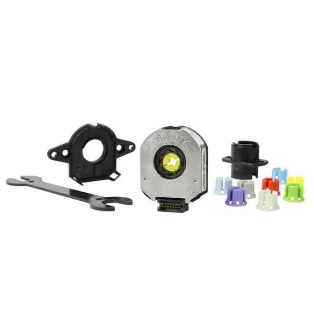
AMT20-V KITS
In order to provide maximum flexibility for our customers, the AMT20 series is provided in kit form standard. This allows the user to implement the encoder into a range of
applications using one sku#, reducing engineering and inventory costs.
SLEEVES
ORDERING GUIDE
AMT203X-V
Connector Options:
"blank" = standard connector
S = locking connector
2mm
3mm
1/8 inch
(3.175mm)
4mm
3/16 inch
(4.76mm)
5mm
6mm
1/4 inch
(6.35mm)
8mm
Light Sky
Blue
Orange
Purple
Gray
Yellow
Green
Red
Snow
Blue
BASE
WIDE
BASE
cuidevices.com
TOP
COVER
SHAFT
ADAPTER
TOOL A
TOOL C
�Additional Resources:
Product Page
|
3D Model
CUI DEVICES | SERIES: AMT20 | DESCRIPTION: MODULAR ABSOLUTE ENCODER
date 08/05/2022 | page 4 of 10
ENCODER INTERFACE
PINOUT CONNECTOR
Function
#
AMT203
1
N/A
2
CSB
3
MISO
4
GND
5
SCK
6
+5 V
7
MOSI
8
B
9
N/A
10
A
11
N/A
12
Z
13
N/A
14
N/A
STANDARD
CONNECTOR OPTION
LOCKING
CONNECTOR OPTION
B
13 11 9
7
5
3
1
14 12 10 8
6
4
2
B
13 11 9
DETAIL B
SCALE 4 : 1
7
5
3
1
14 12 10 8
6
4
2
DETAIL B
SCALE 4 : 1
Mating Connector:
Samtec ISDF-07-D
Mating Connector:
Samtec ISDF-07-D-L
cuidevices.com
�Additional Resources:
Product Page
|
3D Model
CUI DEVICES | SERIES: AMT20 | DESCRIPTION: MODULAR ABSOLUTE ENCODER
date 08/05/2022 | page 5 of 10
MECHANICAL DRAWING
AMT203
units: mm
tolerance: ±0.1
10.34 0.407
R15.49 0.610
15.30 0.602
15.33 0.604
37.39 1.472
10.93 0.430
28.58 1.125
AMT203 WIDE BASE
units: mm
tolerance: ±0.1
10.34 0.407
R15.49 0.610
15.30 0.602
15.33 0.604
37.39 1.472
28.58 1.125
10.93 0.430
52.70 2.075
cuidevices.com
�Additional Resources:
Product Page
CUI DEVICES | SERIES: AMT20 | DESCRIPTION: MODULAR ABSOLUTE ENCODER
|
3D Model
date 08/05/2022 | page 6 of 10
MECHANICAL DRAWING (CONTINUED)
MOUNTING HOLE PATTERNS
STANDARD BASE
units: mm[inch]
tolerance: ±0.1
22.00 0.866
21.55 0.848
20.90 0.823
12.60[0.496]
R1.05 0.041
DETAIL A
SCALE 4 : 1
2.00 0.079
(4 PLCS)
2.95 0.116
(2 PLCS)
16.00 0.630
0.275 0.011
A (3 PLCS)
1.70 0.067
(2 PLCS)
19.05 0.750
25.40 1.000
WIDE BASE
units: mm[inch]
tolerance: ±0.1
32.44 1.277
3.00 0.118
(2 PLCS)
2.96
2.87 X 2.96
(2 PLCS)
A
2.87
0.09
DETAIL A
SCALE 4 : 1
46.02 1.812
cuidevices.com
�Additional Resources:
Product Page
|
3D Model
CUI DEVICES | SERIES: AMT20 | DESCRIPTION: MODULAR ABSOLUTE ENCODER
date 08/05/2022 | page 7 of 10
ASSEMBLY PROCEDURE
STEP 1
STEP 2
STEP 3
Align Tool C with
flange on Base
1. Insert Tool A as a spacer that defines the distance to
the mounting surface.
2. Slide appropriate sized Sleeve over shaft all the way down to Tool A.
3. Slide Shaft Adaptor over Sleeve.
4. Use Tool C to press Shaft Adaptor over Sleeve (ensure Shaft Adapter
and Tool C spline alignment) until flush with Tool A.
STEP 4
1. Remove Tools A and C.
2. Place Base on motor, with Tool C used as a centering tool.
STEP 5
1. Snap the Top Cover onto the Base, carefully observing that the
teeth of the Shaft Adaptor align with the grooves in the hub. *
1. Fasten the Base on the motor (Tool C may need to be
rotated to allow for some mounting configurations).
2. Remove Tool C.
* We recommend no more than three cycles of mounting and
removal of the AMT top cover base. Multiple cycles of mounting
and removing the top cover can cause base fatigue over time and
affect encoder performance.
cuidevices.com
1. Align Tool C with flange on Base.
2. Slide Base and Tool C onto motor, centering onto
the Shaft Adapter.
STEP 6
1. Make sure the snaps are fully engaged by pressing
on the Hub with the reverse side of Tool C.
2. When assembly is finished, the Shaft Adaptor, Sleeve
and Rotor Hub should all be flush with the Motor
Shaft rotating freely.
�Additional Resources:
Product Page
|
3D Model
CUI DEVICES | SERIES: AMT20 | DESCRIPTION: MODULAR ABSOLUTE ENCODER
date 08/05/2022 | page 8 of 10
APPLICATION NOTES
ENCODER OPERATIONAL MODE
• Initialization mode: At power up the encoder goes through an initiation and stabilization procedure. This includes microprocessor stabilization and the
program for getting the absolute start position. This takes less than 100 milliseconds.
• Tracking mode:
1.
MCU 12 bit position register is updated from every 48 μs.
2.
For accurate position information without the 48 μs incremental outputs A/B can be used for tracking. These outputs are
operational up to 8000 RPM without speed error.
3.
When using the incremental output there also is a Z index pulse that occurs once per turn.
SERIAL PERIPHERAL INTERFACE COMMANDS
The Serial Peripheral Interface (SPI) bus is a standard serial interface that operates in full duplex mode. It consists of 4 signals:
1.
MOSI: Master Out Slave In
2.
MISO: Master In Slave Out
3.
SCK: Serial Clock
4.
CSB: Chip Select (active low)
SPI BUS
The SPI bus transfers multiples of 8 bits in a frame. Data is captured on the rising edge of SCK and the output data is changed after the falling edge of
SCK.
MISO
LSB
MSB
Terminology
SCK
MOSI
CSB
LSB
MSB
MSB = most significant byte
LSB = least significant byte
msb = most significant bit
lsb = least significant bit
Setup
Serial Peripheral Interface Bus (SPI) on AMT203 Timing Diagram
(Figure 1)
The data out on MISO is valid once CSB goes low. The MOSI data is valid after the falling edge of SCK. The encoder drives data out on MISO for as long as
CSB is low.
Normally, CSB goes low, then after 8 clock cycles the command is interpreted. CSB high resets the clock counter, and terminates any command
sequence.
cuidevices.com
�Additional Resources:
Product Page
|
3D Model
CUI DEVICES | SERIES: AMT20 | DESCRIPTION: MODULAR ABSOLUTE ENCODER
date 08/05/2022 | page 9 of 10
APPLICATION NOTES (CONTINUED)
SPI COMMANDS
All commands are 8 bits long. The msb is shifted in first, and is the leftmost bit shown in Figure 1.
Encoder Protocol Considerations:
The encoder is designed to operate with a high speed SPI link, in full duplex mode. This implies the host can issue commands and read data as quickly
as necessary but there has to be an acknowledgement from the slave just before the data is transferred.
First the host will issue a command, then the encoder may respond with wait responses (0xA5) until ready. Once ready the encoder will echo the original
command received from the master, followed by the requested data.
For example, to read the position the master will send the rd_pos command (0x10), it will then send no operation commands (nop_a5, 0x00) until it
receives the original rd_pos command back. Once it receives the rd_pos response from the encoder, it knows that the next two bytes of data will be the
MSB and the LSB respectively. To receive those two bytes the master will send two no operation commands.
It is recommended that the master leave a 20 μs delay between reads to avoid extending the read time by forcing wait sequences.
Each byte transmitted must be followed by a release of the Chip Select line (CSB).
Command 0x00: nop_a5 (no operation)
This no operation command is ignored by the encoder and simply causes the next byte of data to be read. The encoder will respond with 0xA5 if there is
no remaining data to be sent.
Command 0x10: rd_pos (read position)
This command causes a read of the current position.
To read position this sequence should be followed:
1.
Master sends rd_pos command. Encoder responds with idle character.
2.
Continue sending nop_a5 command while encoder response is 0xA5
3.
If response was 0x10 (rd_pos), send nop_a5 and receive MSB position (lower 4 bits of this byte are the upper 4 of the 12-bit
position)
4.
Send second nop_a5 command and receive LSB position (lower 8 bits of 12-bit positon)
Note that it is possible to overlap commands. For instance, instead of issuing nop_a5 for steps 3 and 4, you could begin another read position sequence
since the position data is already in the buffer. The read and write FIFOs for the streams are 16 bytes long and it is up to the user to avoid overflow.
Command 0x70: set_zero_point (zero set)
This command sets the current position to zero and saves this setting in the EEPROM.
To set the zero point this sequence should be followed:
1.
Send set_zero_point command
2.
Send nop_a5 command while response is not 0x80
3.
A response of 0x80 means that the zero set was successful and the new position offset is stored in EEPROM.
4.
The encoder must be power cycled. If the encoder is not power cycled, the position values will not be calculated off the latest zero position.
When the encoder is powered on next the new offset will be used for the position calculation.
cuidevices.com
�Additional Resources:
Product Page
|
3D Model
CUI DEVICES | SERIES: AMT20 | DESCRIPTION: MODULAR ABSOLUTE ENCODER
date 08/05/2022 | page 10 of 10
REVISION HISTORY
rev.
description
date
1.0
initial release
05/01/2010
1.01
updated pin-out
10/01/2010
1.02
updated application note
01/01/2011
1.03
updated SPI commands
09/16/2011
1.04
addition of shock and incremental output current data, correction of vibration
data, updated part number key
09/30/2011
1.05
updated Part Number Key
03/09/2012
1.06
updated tools
07/13/2012
1.07
added locking connector drawing
02/12/2013
1.08
updated spec
12/09/2013
1.09
updated spec
11/19/2014
1.10
updated spec
05/13/2016
1.11
changed outer mounting holes to be oblong on wide base version, part number
key updated
03/23/2018
1.12
added wide base to kits
10/18/2018
1.13
brand update
11/21/2019
1.14
added motor shaft tolerance details, updated start-up details
09/10/2021
logo, datasheet style update
08/05/2022
1.15
The revision history provided is for informational purposes only and is believed to be accurate.
CUI Devices offers a one (1) year limited warranty. Complete warranty information is listed on our website.
CUI Devices reserves the right to make changes to the product at any time without notice. Information provided by CUI Devices is believed to be accurate
and reliable. However, no responsibility is assumed by CUI Devices for its use, nor for any infringements of patents or other rights of third parties which may
result from its use.
CUI Devices products are not authorized or warranted for use as critical components in equipment that requires an extremely high level of reliability. A
critical component is any component of a life support device or system whose failure to perform can be reasonably expected to cause the failure of the life
support device or system, or to affect its safety or effectiveness.
cuidevices.com
�


 工商网监
湘ICP备2023018690号
工商网监
湘ICP备2023018690号
