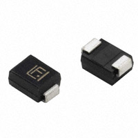
Technical Data 11212
Effective November 2020
P6SMB
600 W Transient voltage suppressor
Applications
Product features
•
Low profile SMB package
•
Excellent clamping capability
•
600 W peak pulse power capability at
10/1000 μs waveform
•
Typical IR less than 1 μA above 12 V
•
Fast response time: typically less than 1.0 ps
from 0 V to VBR minimum
•
High temperature reflow soldering:
+260 °C /40 s at terminal
•
Plastic package meets UL 94 V-0 flammability
rating
•
Meets moisture sensitivity level (MSL) level 1
•
Terminal: Solder plated leads,
solderable per J-STD-002
•
For surface mounted applications in order to
optimize board space
•
UL 497B recognized.
File No. : E198449 Guide QVGQ2
PIN configuration
•
Consumer electronics
•
Telecommunications
•
Computing and servers
•
Appliances
•
Industrial automation
•
Mobile and wearables
Environmental compliance and general
specifications
HALOGEN
Pb HF
FREE
Ordering part number
P6SMB 6-8 C A
Family name
VR voltage
(“-” indicates decimal point)
Bi-/Uni-Directional
(Blank=Uni, C=Bi)
Voltage tolerance
P6SMB
600 W Transient voltage suppressor
Technical Data 11212
Effective November 2020
Absolute maximum ratings
(+25 °C, RH=45%-75%, unless otherwise noted)
Parameter
Symbol
Value
Unit
TSTG/ TJ
-55 to +150
°C
Steady state power dissipation at TL= +75 °C
PM(AV)
5.0
W
Peak pulse power dissipation on 10/1000 μs
waveform
PPP
600
W
Maximum instantaneous forward voltage at
100 A for unidirectional
VF
5.0
V
Peak forward surge current, 8.3 ms single
half sine wave1
IFSM
100
A
Typical thermal resistance junction to lead
R
JL
20
°C/W
Typical thermal resistance junction to ambient
R
JA
100
°C/W
Storage operating junction temperature range
1. Measured on 8.3 ms single half sine wave or equivalent square wave for unidirectional device only,
duty cycle = 4 per minute maximum
Mechanical parameters, pad layout- mm
Millimeters
Dimension Minimum
Part marking
Inches
Maximum
Minimum
Maximum
A
3.30
3.94
0.130
0.155
B
4.30
4.80
0.169
0.189
C
1.90
2.20
0.075
0.087
D
0.95
1.52
0.037
0.060
E
5.20
5.60
0.205
0.220
F
0.051
0.203
0.002
0.008
G
0.15
0.31
0.006
0.012
H
2.10
2.40
0.083
0.094
J
2.20
K
L
0.087
2.60
0.102
2.30
Packaging information (mm)
Cathode band (Uni-polar only)
Part marking: xxxx = Date code
yyyy- Refer to marking designator
listed in Electrical Characteristics table
0.091
Dimension
Millimeters
Inches
Drawing not to scale.
A0
3.76 ± 0.3
0.148 ± 0.012
Supplied in tape and reel packaging, 3,000 parts per 13” diameter reel
(EIA-481 compliant)
B0
5.69 ± 0.3
0.224 ± 0.012
C
330.0
13.0
D0
1.55 ± 0.1
0.061 ± 0.004
E
1.75 ± 0.2
0.069 ± 0.008
E1
13.3 ± 0.3
0.524 ± 0.012
F
5.5 ± 0.2
0.217 ± 0.008
P0
4.00 ± 0.2
0.157 ± 0.008
P1
8.00 ± 0.2
0.315 ± 0.008
P2
2.00 ± 0.2
0.079 ± 0.008
W
12.0 ± 0.2
0.472 ± 0.008
W1
15.7 ± 2.0
0.618 ± 0.079
2
www.eaton.com/electronics
Technical Data 11212
P6SMB
600 W Transient voltage suppressor
Effective November 2020
Electrical characteristics (+25 °C)
Part number
Uni-polar
Bi-polar
Marking
Uni
Bi
VR
(V)
IR @ VR
(μA)
VBR @ IT
min (V)
max (V)
IT
(mA)
VC @ IPP
max (V)
IPP
(A)
P6SMB6-8A
P6SMB6-8CA
6V8A
6V8C
5.8
150
6.45
7.14
10
10.5
58.1
P6SMB7-5A
P6SMB7-5CA
7V5A
7V5C
6.4
120
7.13
7.88
10
11.3
54
P6SMB8-2A
P6SMB8-2CA
8V2A
8V2C
7.02
50
7.79
8.61
10
12.1
50.4
P6SMB9-1A
P6SMB9-1CA
9V1A
9V1C
7.78
20
8.65
9.55
1
13.4
45.5
P6SMB10A
P6SMB10CA
10A
10C
8.55
10
9.5
10.5
1
14.5
42.1
P6SMB11A
P6SMB11CA
11A
11C
9.4
5
10.5
11.6
1
15.6
39.1
P6SMB12A
P6SMB12CA
12A
12C
10.2
2
11.4
12.6
1
16.7
36.5
P6SMB13A
P6SMB13CA
13A
13C
11.1
1
12.4
13.7
1
18.2
33.5
P6SMB15A
P6SMB15CA
15A
15C
12.8
1
14.3
15.8
1
21.2
28.8
P6SMB16A
P6SMB16CA
16A
16C
13.6
1
15.2
16.8
1
22.5
27.1
P6SMB18A
P6SMB18CA
18A
18C
15.3
1
17.1
18.9
1
25.2
24.2
P6SMB20A
P6SMB20CA
20A
20C
17.1
1
19
21
1
27.7
21.7
P6SMB22A
P6SMB22CA
22A
22C
18.8
1
20.9
23.1
1
30.6
19.7
P6SMB24A
P6SMB24CA
24A
24C
20.5
1
22.8
25.2
1
33.2
18.4
P6SMB27A
P6SMB27CA
27A
27C
23.1
1
25.7
28.4
1
37.5
16.3
P6SMB30A
P6SMB30CA
30A
30C
25.6
1
28.5
31.5
1
41.4
14.7
P6SMB33A
P6SMB33CA
33A
33C
28.2
1
31.4
34.7
1
45.7
13.3
P6SMB36A
P6SMB36CA
36A
36C
30.8
1
34.2
37.8
1
49.9
12.2
P6SMB39A
P6SMB39CA
39A
39C
33.3
1
37.1
41
1
53.9
11.3
P6SMB43A
P6SMB43CA
43A
43C
36.8
1
40.9
45.2
1
59.3
10.3
P6SMB47A
P6SMB47CA
47A
47C
40.2
1
44.7
49.4
1
64.8
9.4
P6SMB51A
P6SMB51CA
51A
51C
43.6
1
48.5
53.6
1
70.1
8.7
P6SMB56A
P6SMB56CA
56A
56C
47.8
1
53.2
58.8
1
77
7.9
P6SMB62A
P6SMB62CA
62A
62C
53
1
58.9
65.1
1
85
7.2
P6SMB68A
P6SMB68CA
68A
68C
58.1
1
64.6
71.4
1
92
6.6
P6SMB75A
P6SMB75CA
75A
75C
64.1
1
71.3
78.8
1
103
5.9
P6SMB82A
P6SMB82CA
82A
82C
70.1
1
77.9
86.1
1
113
5.4
P6SMB91A
P6SMB91CA
91A
91C
77.8
1
86.5
95.5
1
125
4.9
P6SMB100A
P6SMB100CA
100A
100C
85.5
1
95
105
1
137
4.5
P6SMB110A
P6SMB110CA
110A
110C
94
1
105
116
1
152
4
P6SMB120A
P6SMB120CA
120A
120C
102
1
114
126
1
165
3.7
P6SMB130A
P6SMB130CA
130A
130C
111
1
124
137
1
179
3.4
P6SMB150A
P6SMB150CA
150A
150C
128
1
143
158
1
207
2.9
P6SMB160A
P6SMB160CA
160A
160C
136
1
152
168
1
219
2.8
P6SMB170A
P6SMB170CA
170A
170C
145
1
162
179
1
234
2.6
P6SMB180A
P6SMB180CA
180A
180C
154
1
171
189
1
246
2.5
P6SMB200A
P6SMB200CA
200A
200C
171
1
190
210
1
274
2.2
P6SMB220A
P6SMB220CA
220A
220C
185
1
209
231
1
328
1.9
P6SMB250A
P6SMB250CA
250A
250C
214
1
237
263
1
344
1.8
P6SMB300A
P6SMB300CA
300A
300C
256
1
285
315
1
414
1.5
P6SMB350A
P6SMB350CA
350A
350C
300
1
332
368
1
482
1.3
P6SMB400A
P6SMB400CA
400A
400C
342
1
380
420
1
548
1.1
P6SMB440A
P6SMB440CA
440A
440C
376
1
418
462
1
602
1
P6SMB480A
P6SMB480CA
480A
480C
408
1
456
504
1
658
0.9
P6SMB510A
P6SMB510CA
510A
510C
434
1
485
535
1
698
0.9
P6SMB540A
P6SMB540CA
540A
540C
460
1
513
567
1
740
0.8
P6SMB600A
P6SMB600CA
600A
600C
512
1
570
630
1
828
0.75
www.eaton.com/electronics
3
P6SMB
600 W Transient voltage suppressor
Technical Data 11212
Effective November 2020
Ratings and V-I characteristic curves (+25 °C unless otherwise noted)
V- I curve characteristics (Uni-directional)
V- I curve characteristics (Bi-directional)
Surge waveform: 10/1000 μs
VR: Stand-off voltage -- Maximum voltage that can be applied
VBR: Breakdown voltage
VC: Clamping voltage -- Peak voltage measured across the suppressor at a specified IPP
IR: Reverse leakage current
IT: Test current
VF: Forward voltage drop for Uni-directional TVS diode
Pulse derating curve
150
tr = rise time to peak value
td = decay time to half value
IPPM (% IRSM)
tr=10 μs
100
Peak value
Half value
50
0
0
td
1.0
2.0
3.0
4.0
t (ms)
100
Ppp (kW)
600 W at 10/1000 μs +25 °C
10
1.0
0.1
0.001
0.01
0.1
td-Pulse width (ms)
www.eaton.com/electronics
100
80
60
40
20
0
0
25
50
75
100
125
150
TJ-Initial junction temperature (°C)
Peak pulse power dissipation vs. pulse width
4
PPP derating in percentage (%)
Pulse waveform
1.0
10
175
Technical Data 11212
P6SMB
600 W Transient voltage suppressor
Effective November 2020
Solder reflow profile
TP
TC -5°C
tP
Max. Ramp Up Rate = 3°C/s
Max. Ramp Down Rate = 6°C/s
Temperature
TL
Preheat
A
T smax
t
Table 1 - Standard SnPb solder (Tc)
Package
thickness
Volume
mm3
很抱歉,暂时无法提供与“P6SMB15CA”相匹配的价格&库存,您可以联系我们找货
免费人工找货