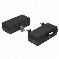
2N7002K
N-CHANNEL ENHANCEMENT MODE FIELD EFFECT TRANSISTOR
FEATURES
N-channel Enhancement Mode Field Effect
Transistor, Designed For High Speed Pulse
Amplifier And Drive Application, Which Is
Manufactured By The N-Channel DMOS Process.
ESD MIL-STD 833, ±2.5KV Contact Discharge
Compliant Protection
D
MECHANICAL DATA
S
Available in SOT-23 Package
Solderability:MIL-STD-202, Method 208
G
Full RoHS Compliance
ORDERING INFORMATION
PART NUMBER
2N7002K□-T3
PACKAGE
SHIPPING
MARKING CODE
SOT-23
Tape Reel
7002K
Notes:
1. □: none is for Lead Free package;
“G” is for Halogen Free package.
THERMAL DATA
PARAMETER
SYMBOL
VALUES
UNIT
Thermal Resistance, Junction-to-Ambient
RθJA
357
°C/W
Thermal Resistance, Junction-to-Case
RθJC
90
°C/W
Notes:
2. RθJA is the sum of the junction-to-case and case-to-ambient thermal resistance where the case thermal reference is defined
as the solder mounting surface of the drain pins. RθJC is guaranteed by design while RθCA is determind by the user’s board
2
design. The value of RθJA is measured with device mounted on 1 in FR-4 board with 2 oz copper.
STD_V3.0
PAGE.1
�2N7002K
ABSOLUTE MAXIMUM RATINGS
TA = 25°C, unless otherwise noted. (Note 3)
PARAMETER
SYMBOL
VALUE
UNIT
Drain-Source Voltage
VDSS
60
V
Gate-Source Voltage
VGSS
±20
V
Drain Current (Pulsed) (Note 4)
IDM
800
mA
Drain Current (Continuous)
ID
300
mA
Maximum Power Dissipation
PD
350
mW
Operating Junction Temperature Range
TJ
-55 to +150
°C
Tstg
-55 to +150
°C
Storage Temperature Range
Notes:
3. Absolute maximum ratings are those values beyond which the device could be permanently damaged. Absolute maximum
ratings are stress ratings only and functional device operation is not implied.
4. Pulse width limited by maximum junction temperature.
STD_V3.0
PAGE.2
�2N7002K
ELECTRICAL CHARACTERISTICS
TC = 25°C, unless otherwise noted.
PARAMETER
SYMBOL
TEST CONDITIONS
MIN
TYP
MAX UNIT
OFF CHARACTERISTICS
Drain-Source Breakdown Voltage
BVDSS
VGS = 0V, ID = 10A
Drain-Source Leakage Current
IDSS
VGS = 0V, VDS = 60V, TJ = 25°C
Gate- Source Leakage Current
±IGSS
VDS = 0V, VGS = ±20V
Gate Threshold Voltage
VGS(th)
VDS = VGS, ID = 250A
Static Drain-Source On Resistance
RDS(ON)
VGS = 10V, ID = 300mA
60
V
1
A
±10
A
1.7
2.5
V
2.0
3.0
Ω
(Note 5)
ON CHARACTERISTICS
1.0
DYNAMIC CHARACTERISTICS
Input Capacitance
Ciss
Output Capacitance
Coss
Reverse Transfer Capacitance
Crss
50
VDS = 25V, VGS = 0V, f = 1.0MHz
25
pF
5.0
SWITCHING CHARACTERISTICS
Turn-On Delay Time
td(on)
Turn-On Rise Time
tr
Turn-Off Delay Time
td(off)
Turn-Off Fall Time
tf
6
VDD = 30V, ID = 200mA,
RL=150Ω, VGEN=10V
5
nS
25
RGEN=25Ω
15
DRAIN-SOURCE DIODE CHARACTERISTICS AND MAXIMUM RATINGS
Drain-source Diode Forward Voltage
Transfer Admittance
VSD
VGS = 0V, IS = 300mA
︱Yfs︱
ID = 200mA, VDS = 15V
0.85
80
1.5
V
mS
Notes:
5. Pulse test:Pulse width ≦300μS, Duty cycle ≦2%
STD_V3.0
PAGE.3
�2N7002K
TYPICAL PERFORMANCE CHARACTERISTICS
Output Characteristics
Drain-Source On Resistance
1.0
4.0
RDS(ON) - On Resistance (Ω)
0.8
ID - Drain Current (A)
3.5
VGS= 4,5,6,8,10 V
3.0 V
0.6
0.4
0.2
2.1V
0.0
0.0 0.5 1.0 1.5 2.0 2.5 3.0 3.5 4.0 4.5 5.0
3.0
VGS= 4.5V
2.5
2.0
VGS= 10 V
1.5
1.0
0.5
0.0
0.1 0.2 0.3 0.4 0.5 0.6 0.7 0.8 0.9 1.0
VDS - Drain-Source Voltage (V)
1.6
ID= 0.4 A
2.8
RDS(ON) - On Resistance (Ω)
Gate Threshold Voltage
Transfer Characteristics
2.6
2.4
2.2
2.0
1.8
1.6
1
2
3
4
5
6
7
8
9
10
VGS - Gate-Source Voltage (V)
STD_V3.0
Normalized Threshold Voltage
3.0
ID - Drain Current (A)
IDS = 250 A
1.4
1.2
1.0
0.8
0.6
0.4
0.2
0.0
-50 -25
0
25
50
75 100 125 150
Tj - Junction Temperature (°C)
PAGE.4
�2N7002K
Drain-Source On Resistance
Source-Drain Diode Forward
20
VGS= 10 V
1.8
ID = 0.4 A
IS - Source Current (A)
Normalized On Resistance
2.0
1.6
1.4
1.2
1.0
0.8
10
o
Tj= 150 C
o
Tj =25 C
1
0.6
o
0.4
-50 -25
RON@Tj= 25 C: 1.9
0
25
50
0.1
0.0
75 100 125 150
Tj - Junction Temperature (°C)
C - Capacitance (pF)
45
40
35
Ciss
30
25
20
15
10
Coss
5
0
Crss
0 2 4 6 8 10 12 14 16 18 20 22 24 26 28 30
VDS - Drain-Source Voltage (V)
STD_V3.0
1.2
1.5
1.8
VDS= 10 V
4
Frequency = 1 MHz
50
0.9
Gate Charge
Capacitance
55
0.6
VSD - Source-Drain Voltage (V)
VGS - Gate-Source Voltage (V)
60
0.3
IDS= 0.4 A
3
2
1
0
0
50
100 150 200 250 300 350
QG - Gate Charge (pC)
PAGE.5
�2N7002K
PHYSICAL DIMENSION
Unit:Inch (Millimeter)
SOT-23
STD_V3.0
PAGE.6
�
很抱歉,暂时无法提供与“2N7002K”相匹配的价格&库存,您可以联系我们找货
免费人工找货