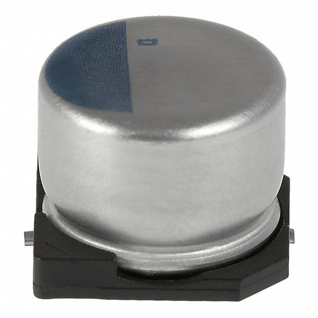
CONDUCTIVE POLYMER ALUMINUM SOLID CAPACITORS
TM
NPCAP
Surface Mount
PXH
-
Series
・Super low ESR, impedance and high heat resistance have been obtained by using conductive polymer as electrolyte.
・Suitable for DC-DC converters, voltage regulators and decoupling applications.
・Endurance : 125℃ 1,000 hours
・Rated voltage range : 2.5 to 20Vdc, Capacitance range : 22 to 1,000µF
・Case size range :φ6.3×5.8L to φ10×7.7L
・Solvent resistant type (see PRECAUTIONS AND GUIDELINES)
・RoHS2 Compliant
・Halogen Free
PXH
Higher temperature
PXA
◆SPECIFICATIONS
Items
Characteristics
Category
Temperature Range
Rated Voltage Range
Capacitance Tolerance
Leakage Current
-55 to +125℃
2.5 to 20Vdc
±20% (M)
Shall not exceed values shown in STANDARD RATINGS.
*Note
Dissipation Factor
(tanδ)
Low Temperature
Characteristics
(Max. Impedance Ratio)
Endurance
(at 20℃, 120Hz)
(at 20℃ after 2 minutes)
0.12 max.
(at 20℃, 120Hz)
Z(-25℃)/Z(+20℃)≦1.15
Z(-55℃)/Z(+20℃)≦1.25
(at 100kHz)
The following specifications shall be satisfied when the capacitors are restored to 20℃ after the rated voltage is applied for 1,000 hours
at 125℃.
Appearance
No significant damage
Capacitance change
≦±20% of the initial value
D.F. (tanδ)
≦200% of the initial specified value
ESR
≦200% of the initial specified value
Leakage current
≦The initial specified value
The following specifications shall be satisfied when the capacitors are restored to 20℃ after subjecting them to the DC rated voltage at
60℃, 90 to 95% RH for 1,000 hours.
Appearance
No significant damage
Capacitance change
≦±20% of the initial value
D.F. (tanδ)
≦150% of the initial specified value
ESR
≦150% of the initial specified value
Leakage current
≦The initial specified value
The capacitors shall be subjected to 1,000 cycles each consisting of charge with the surge voltage specified at 125℃ for 30 seconds
through a protective resistor(R=1kΩ) and discharge for 5 minutes 30 seconds.
Rated voltage (Vdc)
2.5
4.0
6.3
10
16
20
Surge voltage (Vdc)
2.9
4.6
7.2
12
18
23
Bias Humidity
Surge Voltage
Appearance
No significant damage
Capacitance change
≦±20% of the initial value
D.F. (tanδ)
≦150% of the initial specified value
ESR
≦150% of the initial specified value
Leakage current
≦The initial specified value
The following specifications shall be satisfied when the solder temperature is reduced back to 20°C to measure dip resistance after
soldering has been performed under the recommended soldering conditions.
Appearance
No significant damage
Capacitance value
Within the specified tolerance range
D.F. (tanδ)
≦The initial specified value
ESR
≦The initial specified value
Leakage current
≦The initial specified value (Voltage
treatment)
Soldering Heat
*Note : If any doubt arises, measure the leakage current after the following voltage treatment.
Voltage treatment : DC rated voltage is applied to the capacitors for 120 minutes at 125℃.
◆DIMENSIONS [mm]
EX) 20V22µF
W
B±0.2
P
C±0.2
Code : A
φD±0.5
● Terminal
0.3max.
◆MARKING
Size code
F61
H70
J80
φD
6.3
8
10
L
5.8
6.7
7.7
A
B
C
6.6 6.6 7.2
8.3 8.3 9.0
10.3 10.3 11.0
W
0.5 to 0.8
0.7 to 1.1
0.7 to 1.1
P
1.9
3.1
4.5
H39F
22
20V
A±0.2
L±0.3
Product specifications in this catalog are subject to change without notice.Request our product specifications before purchase and/or use. Please use our products based on the information contained in this catalog and product specifications.
CAT. No. E1001X 2023
�CONDUCTIVE POLYMER ALUMINUM SOLID CAPACITORS
TM
NPCAP
Surface Mount
PXHSeries
-
◆PART NUMBERING SYSTEM
1
2
3
4
A PXH
5
6
7
8
9
10
A RA
11
12
13
14
M
15
16
17
18
G
Supplement code
Size code
Capacitance tolerance code
Capacitance code (ex. 22µF:220,100µF:101)
Taping code
Terminal code
Voltage code (ex. 6.3V:6R3,10V:100)
Series code
Category
Please refer to "Product code guide (conductive polymer type)"
◆STANDARD RATINGS
WV
(Vdc)
2.5
4
6.3
10
16
20
Cap
(µF)
220
560
1,000
150
220
680
82
100
150
220
470
56
120
150
330
39
82
150
180
22
47
82
Size code
Leakage current
ESR
(µA max./after 2min.) (mΩ max./20℃, 100k to 300kHz)
F61
H70
J80
F61
H70
J80
F61
F61
H70
H70
J80
F61
H70
H70
J80
F61
H70
J80
J80
F61
H70
J80
110
280
500
120
176
544
103
126
189
277
592
112
240
300
660
125
262
480
576
88.0
188
328
35
30
25
35
30
25
40
40
30
30
25
45
35
35
30
50
40
35
35
60
45
45
Rated ripple current
(mArms/100kHz)
-55℃≦Tx≦+105℃*1
2,500
3,100
3,700
2,450
3,020
3,700
2,400
2,400
3,020
3,020
3,700
2,250
2,800
2,800
3,700
2,050
2,700
3,020
3,020
1,650
2,000
2,400
Part No.
+105℃<Tx≦+125℃*1
770
960
1,100
770
960
1,100
720
720
960
960
1,100
680
880
880
1,010
650
830
930
930
590
780
820
APXH2R5ARA221MF61G
APXH2R5ARA561MH70G
APXH2R5ARA102MJ80G
APXH4R0ARA151MF61G
APXH4R0ARA221MH70G
APXH4R0ARA681MJ80G
APXH6R3ARA820MF61G
APXH6R3ARA101MF61G
APXH6R3ARA151MH70G
APXH6R3ARA221MH70G
APXH6R3ARA471MJ80G
APXH100ARA560MF61G
APXH100ARA121MH70G
APXH100ARA151MH70G
APXH100ARA331MJ80G
APXH160ARA390MF61G
APXH160ARA820MH70G
APXH160ARA151MJ80G
APXH160ARA181MJ80G
APXH200ARA220MF61G
APXH200ARA470MH70G
APXH200ARA820MJ80G
*1 Tx : Ambient temperature(℃)
◆RATED RIPPLE CURRENT MULTIPLIERS
・Frequency Multipliers
Frequency(Hz)
2.5 to 6.3Vdc
10 to 20Vdc
120
0.05
0.05
1k
0.30
0.25
10k
0.55
0.55
50k
0.70
0.55
100k to 500k
1.00
1.00
Product specifications in this catalog are subject to change without notice.Request our product specifications before purchase and/or use. Please use our products based on the information contained in this catalog and product specifications.
CAT. No. E1001X 2023
�CONDUCTIVE POLYMER ALUMINUM SOLID CAPACITORS
Product Guide
■ Always read "Notes on Use" before using the product in order to enable you to use the product correctly and prevent any faults
and accidents from occurring.
■ Request the Product Specification on the product of NIPPON CHEMI-CON CORPORATION to refer to it as well as this brochure
prior to the order of the products. Some specific notes on use of the ordered product may be described in the specifications.
■ The products listed in this catalog are designed and manufactured for general electronics equipment use and are not intended for
use in applications that can adversely affect human life; where the malfunction of equipment may cause damage to life or
property. In addition, our products are not intended to be used in specific applications that may cause a major social impact.
Please consult with us in advance of usage of our products in the following listed applications. ① Aerospace equipment ② Power
generation equipment such as thermal power, nuclear power etc. ③ Medical equipment ④ Transport equipment (automobiles,
trains, ships, etc.) ⑤ Transportation control equipment ⑥ Disaster prevention / crime prevention equipment ⑦ Highly publicized
information processing equipment ⑧ Submarine equipment ⑨ Other applications that are not considered general-purpose
applications.
■ The circuits described as examples in this catalog and the "delivery specifications" are featured in order to show the operations
and usage of our products, however, this fact does not guarantee that the circuits are available to function in your equipment
systems. We are not in any case responsible for any failures or damage caused by the use of information contained herein. You
should examine our products, of which the characteristics are described in the "delivery specifications" and other documents, and
determine whether or not our products suit your requirements according to the specifications of your equipment systems.
Therefore, you bear final responsibility regarding the use of our products.
Please make sure that you take appropriate safety measures such as use of redundant design and malfunction prevention
measures in order to prevent fatal accidents and/or fires in the event any of our products malfunction.
■ We strongly recommend our customers to purchase Nippon Chemi-Con products only through our official sales channels. We
assume no responsibility for any defects or damages caused by using products purchased from outside our official sales channel
or of counterfeit goods. In addition, we will ask the customer to pay the investigation cost for products purchased outside our
official sales channel.
■ We reserve the right to discontinue production and delivery of products. We do not guarantee that all the products included in this
catalog will be available in the future.
The aforementioned does not apply in the case of individual agreements deviating from the foregoing for customer-specific
products
■ We continually strive to improve the quality and reliability of our products, but in any case that our product does not meet our
published specifications, please stop using it promptly and contact us immediately. As for compensation for non-conforming
goods delivered by Chemi-Con, we will limit it only to goods found in non-compliance of our published specifications. This may be
accomplished by a no cost replacement of non-conforming individual products, a credit of the piece price paid per each individual
non-conforming product, or in other ways deemed necessary.
In addition, we have an established system with enhanced traceability, therefore we will limit the applicable lot items for any
potential compensation.
Part Numbering System
Part Numbering System (Appendix)
Standardization
Available Items by Manufacturing Locations
Environmental Measures
Technical Note
Precautions and Guidelines
Recommended Soldering Conditions
Taping, Lead-preforming, Terminal and Packaging Options
Product specifications in this catalog are subject to change without notice.Request our product specifications before purchase and/or use. Please use our products based on the information contained in this catalog and product specifications.
CAT. No. E1001X 2023
�


 工商网监
湘ICP备2023018690号
工商网监
湘ICP备2023018690号
