GE
Data Sheet
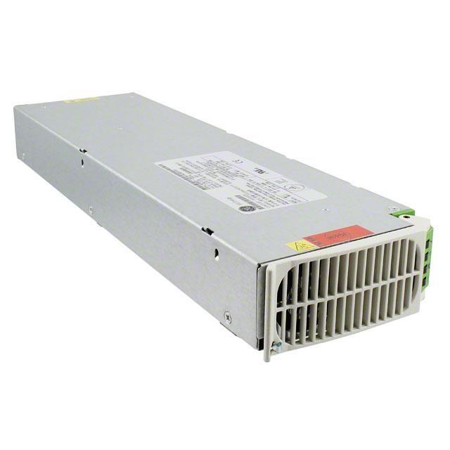
CP2725AC48TEZ-FB Compact Power Line High Efficiency Rectifier
Input: 100-120/220-240 Vac; Output: 2725W1 @ 52Vdc; 5 Vdc @ 4W
Features
Applications
Wide band power amplifiers
Efficiency 95%
Output overvoltage and overload protection
Compact 1RU form factor providing 30 W/in3
2725W @ 52V from nominal 220 – 240Vac
1200W from nominal 100 – 120Vac (for Vo > 42Vdc)
Output voltage programmable from 18V – 53Vdc
PMBus compliant dual I2C and RS485 serial busses
Power factor correction (meets EN/IEC 61000-3-2 and EN
60555-2 requirements)
AC Input overvoltage and undervoltage protection
Over-temperature warning and protection
Redundant, parallel operation with active load sharing
Redundant +5V Aux power
Remote ON/OFF
Hot insertion/removal (hot plug)
Four front panel LED indicators
UL* Recognized to UL60950-1, CAN/ CSA† C22.2 No. 609501, and VDE‡ 0805-1 Licensed to IEC60950-1
CE mark meets 2006/95/EC directive§
Internally controlled Variable-speed fan
RoHS 6 compliant
Special Foldback Curve
Description
The CP2725AC48TEZ-FB Rectifier has an extremely wide programmable output voltage capability and fold-back current
limiting features. High-density front-to-back airflow is designed for minimal space utilization and is highly expandable for
future growth. This custom rectifier incorporates both RS485 and dual-redundant I2C communications busses that allow it
to be used in a broad range of applications. Feature set flexibility makes this rectifier an excellent choice for a set of
applications requiring operation over a wide output voltage range.
*
†
‡
§
UL is a registered trademark of Underwriters Laboratories, Inc.
CSA is a registered trademark of Canadian Standards Association.
VDE is a trademark of Verband Deutscher Elektrotechniker e.V.
This product is intended for integration into end-user equipment. All the required procedures for CE marking of end-user equipment should be
followed. (The CE mark is placed on selected products.)
** ISO is a registered trademark of the International Organization of Standards.
1
High line operation. The unit current limits below 52V and therefore the available output power below 52V operation is reduced.
January 7, 2013
©2013 General Electric Company. All rights reserved.
�GE
Data Sheet
CP2725AC48TEZ-FB Rectifier
Input: 100-120/220-240 Vac; Output: 2725W1 @ 52Vdc; 5 Vdc @ 4W
Electrical Specifications
Input
Parameter
Min
Typ
Max
Startup Input Voltage
Low-line Operation
High-line Operation
Units
Notes
90
200
Operating Voltage Range
Low-line Configuration
High-line Configuration
90
200
Surges (no damage)
305
Input Frequency
47
100, 110, 120
220 - 240
Input Current
140
265
Vac
66
Hz
12
13.5
A
At 110 Vac
At 240 Vac
Inrush Transient
25
30
Apk
Measured at 25°C for all line conditions; does not
include X-Capacitors charging.
Input Leakage Current
2.5
3.5
mA
Measured at 265Vac, 60Hz
0.98
From 50% to 100% (2725W @ HL, 1200W @ LL). load
95
%
With or’ing function, aux 5V output, dual/redundant
I2C and RS485 communications and POE isolation
%
>20% load
Test condition: input; 240Vac, 60hz, output; 52Vdc
ms
48Vdc, Measurement starts at zero crossing of the ac
voltage, and voltage decayed to 40V.
For loads below 1200W.
Power Factor
0.96
20 – 90% of FL
93
>38V
85
Efficiency2
20
Holdup
30
Ride thru
Power Fail Warning3
1/2
1
cycle
3
5
ms
Tested at nominal 115V and 230V . Complies to
CISPR24 standards
Alarm issued via PFW signal going LO 5 ms prior to
the main output decaying below 40Vdc.
Main Output
Parameter
Output Power
Min
Default Set point
Overall Regulation4
Output Voltage Set Range
Output current
2
3
4
Typ
Max
1200
2725
Units
W
48
Vdc
Notes
Above 52Vdc from nominal 90-120Vac upto 55°C.
Above 52Vdc from nominal 200-265Vac upto 55°C
Output floats with respect to frame ground.
-1
-2
+1
+2
%
0 – 45C, minimum load 2.5A
> 45C
18
53
Vdc
Analog margining and RS485
18
53
Vdc
Set by I2C
1
1
23
52.4
A
1200W @ 52V @ 90-120Vac.
2725W @ 52V @ 200-240Vac.
At 52Vdc, 240Vrms and 25C.
Internal protection circuits may override the PFW signal and may trigger an immediate shutdown.
Includes all variations due to specified load range, drift, and environmental conditions.
January 7, 2013
©2013 General Electric Company. All rights reserved.
Page 2
�GE
Data Sheet
CP2725AC48TEZ-FB Rectifier
Input: 100-120/220-240 Vac; Output: 2725W1 @ 52Vdc; 5 Vdc @ 4W
Electrical Specifications (continued)
Main Output (continued)
Parameter
Current Share
Min
VO > 42V
VO < 42V
Typ
-5
-10
Output Ripple
RMS (5Hz to 20MHz)
Peak-to-Peak (5Hz to 20MHz)
60
External Bulk Load Capacitance
0
Turn-On
Delay
Rise Time - Standard (PMBus)
-Telecom (RS-485)5
Overshoot
Max
Notes
%FL
Compared to the average output current delivered by a
set of Rectifiers. Loads > 50% FL
100
500
mVrms
mVp-p
Measured with 20MHz bandwidth under any condition of
loading. Minimum load is 1A.
5,000
F
2
s
ms
s
%
5
100
5
Load Step Response
I
V
Response Time
Units
5
10
50
2.0
2
%FL
Vdc
ms
Power Limit – high line
2725
W
Power limit – low line
1200
W
External capacitance can be increased but the rectifier
will not meet its turn-ON rise time requirement.
Monotonic Turn_On from 30% to 100% of Vnom above 5°C operation. Monotonic Turn_On from 60% to 100% of
Vnom below -5°C operation.
I/t slew rate 1A/µs.
Settling time to within regulation requirements.
Minimum load of 2.5 amperes required.
Down to 51Vdc
The overload current limit threshold should be set 5% above the load envelope shown here
Permissible
Load
Boundary
Contract terms are for supporting all loads inside the load map. The customer will develop a control interface which
maintains the operating voltage and current so as to not exceed the load map.
System Power
Up
5
Units should be able to be plugged in one at a time and guarantee system start up. Units should stay in current limit
for approximately 20 seconds to guarantee restart.
Below -5°C, the rise time is approximately 5 minutes to protect the bulk capacitors.
January 7, 2013
©2013General Electric Company. All rights reserved.
Page 3
�GE
Data Sheet
CP2725AC48TEZ-FB Rectifier
Input: 100-120/220-240 Vac; Output: 2725W1 @ 52Vdc; 5 Vdc @ 4W
Electrical Specifications (continued)
Main Output (continued)
Over-voltage
200msec delayed shutdown to be implemented.
Instantaneous shutdown above this point.
Vdc
Vdc
60
65
Delayed
Immediate Latchoff
Three restart attempts may be implemented within a one minute window prior to a latched
shutdown
Over-temperature
Warning
Shutdown
Auto-recoverable
5
°C
20
°C
Implemented prior to commencement of an OT
shutdown
Below the maximum rating of the device being
protected
Temperature hysteresis of approximately 10°C provided between shutdown and restart.
Overcurrent events that exceed the envelope by 5% will hiccup continuously at a frequency of approximately once every 20 seconds. For voltage setpoints below 42V, a tracking Under Voltage shutdown occurs at 2 volts below set-point. UV must exhibit for more than 1 second before shutdown. UV
shutdown will exhibit the same 20 second hiccup behavior.
Electrical Specifications (continued)
Auxiliary Output
Parameter
Min
Output Voltage Setpoint
Output Current
Overall Regulation
Units
0.75
A
-10
+5
%
100
mVpk-pk
7
Vdc
175
%FL
50
110
Notes
Vdc
0.005
Over-voltage Clamp
January 7, 2013
Max
5
Ripple and Noise
Over-current Limit
Typ
Within ±5% when load is < 0.5A.
20MHz bandwidth
©2013General Electric Company. All rights reserved.
Page 4
�GE
Data Sheet
CP2725AC48TEZ-FB Rectifier
Input: 100-120/220-240 Vac; Output: 2725W1 @ 52Vdc; 5 Vdc @ 4W
Environmental, EMC, Reliability Specifications
Environmental
Parameter
Min
Ambient Temperature
Operating
Derating
-406
Storage Temperature
Typ
Max
Units
1
55
2
°C
°C
°C
Notes
Air inlet from sea level to 5,000 feet.
Per 1,000 feet above 5,000 feet.
-40
85
Humidity
5
95
%
Relative humidity, non-condensing
Altitude
-60
-200
4000
13000
m
ft
For operation above 2500m (5000 ft.), maximum operating
temperature is derated by 2°C per 305m (1000 ft.).
Shock and Vibration
Earthquake Rating
IPC9592 sections 5.2.8 – 5.2.13
4
Acoustic Noise
55
Zone
Per Telcordia GR-63-CORE, all floors, when installed in CP Shelf.
dBA
Noise is proportional to fan speed, load and ambient temperature.
Harmonic Emissions
Per EN/IEC61000-3-2
Radiated Emissions7
Exceeds FCC and CISPR22 (EN55022) - Class A by a 6dB margin
Conducted Emissions - ac
Exceeds FCC and CISPR22 (EN55022) Class A
Telcordia GR-1089-CORE - Class A by a 6dB margin
ESD
Error free per EN/IEC 61000-4-2 Level 3 (6 kV contact discharge, 8 kV air discharge).
Radiated Immunity
Error free per EN/IEC 61000-4-3 Level 3 (10 V/m).
Electrical Fast Transient Burst
Error free per EN/IEC 61000-4-4 Level 3 (2 kV, 5 kHz repetition rate)
Lightning Surge,
EN/IEC61000-4-5 Level 4 (4 kV common mode, 2 kV differential mode).
ANSI C62.41 Level A3 (6 kV common and differential mode)
Error Free
Damage Free
Line sags and interruptions
IPC9592A issued May 2010 ; 1 cycle interruption or 25% sag (115V, 230V – nominal for UUT) for 2 seconds the
output shall stay above 40Vdc at full load. [Note: An input sag below 80V may cause an immediate shutdown.]
Conducted Immunity
Error free per EN/IEC 61000-4-6 Level 3 (10Vrms).
Reliability (calculated)
Isolation
Input-Chassis/Signals
Input - Output
Output-Chassis
Output-Chassis/Signals
Service Life
6
7
450,000
1500
3000
500
2250
10
Hours
At ambient of 25°C at full load per Telcordia SR-332, issue 2,
Reliability Prediction for Electronic Equipment, Method I Case III.
Vrms
Vrms
Vdc
Vdc
Per EN60950.
Consult factory for testing to this requirement
Internal Lineage standard, GR_947
POE compliant Rectifier, Per IEEE802.3.
Years
25°C ambient, full load excluding fans.
Designed to start and work at an ambient as low as -40°C, but may not meet operational limits until above -5°C
Radiated emissions compliance was met using a Lineage Power shelf. This shelf includes output common and differential mode capacitors that
assist in meeting compliance.
January 7, 2013
©2013General Electric Company. All rights reserved.
Page 5
�GE
Data Sheet
CP2725AC48TEZ-FB Rectifier
Input: 100-120/220-240 Vac; Output: 2725W1 @ 52Vdc; 5 Vdc @ 4W
Status and Control
The Rectifier provides three means for monitor/control: analog
RS485or I2C.
Details of analog controls are provided in this Technical
Requirements under Signal Definitions. GE Energy will provide
separate application notes on the RS485 and I2C protocol for
users to interface to the CPL RECTIFIERs. Contact your local GE
Energy representative for details.
Hot Plug
The Rectifier is designed to accommodate rapid extraction and
reinsertion into either RS485 or I2C based protocol
configurations as set by the protocol pin. The protocol state of
the Rectifier shall reset immediately after disengagement from
the mating connector and the Rectifier will configure itself to
the state set by the protocol pin upon reinsertion.
Control Definitions
All signals are referenced to Logic_GRD unless otherwise noted.
See the Signal Definitions Table at the end of this document for
further description of all the signals.
Input Signals
Margining: Set point of the Rectifier can be changed via this
input pin. Programming can be either a voltage source or a
resistance divider. The margining pin is connected to 3.3Vdc via
a 10kΩ resistor inside the Rectifier. See graphs below.
Module Present Signal: This signal has dual functionality. It can be
used to alert the system when a module is inserted. A 500Ω resistor
is present in series between this signal and Logic_GRD. An external
pull-up should not raise the voltage on the pin above 0.25Vdc.
Above 1Vdc, the write_protect feature of the EEPROM is enabled.
Protocol Select: Establishes the communications mode of the
rectifier, between analog/I2C and RS485 modes. For RS485, connect
10kΩ pull-down resistor to 54_OUT(-DC).
Enable: On/Off control when I2C communications are utilized as
configured by the Protocol pin. This pin must be pulled low to turn
ON the rectifier. The rectifier will turn OFF if either the Enable or the
ON/OFF pin is released. This signal is referenced to Logic_GRD. This
function is not supported in RS485 mode.
ON/OFF: This is a short pin utilized for hot-plug applications to
ensure that the rectifier turns OFF before the power pins are
disengaged. It also ensures that the rectifier turns ON only after the
power pins have been engaged. Must be connected to V_OUT (-DC).
Output Signals
Power Capacity: A HI on this pin indicates that the rectifier delivers
high line rated output power; a LO indicates that the rectifier is
connected to low line configured for 1200W operation.
Power Fail Warning: This signal is HI when the main output is being
delivered and goes LO for the duration listed in this data sheet prior
to the output decaying below the voltage level listed in this data
sheet.
Alert #: I2C interrupt signal.
3.3Vdc
10k
Step
granularity =
137mV
-18
Vcontrol
Vprogram
Output Setpoint (Vdc)
-53
Fan failure, OT shutdown, OV shutdown, Internal fault
RS485 mode default: When the unit is powered ON in RS-485 mode
the default operational state is powered ON. An RS-485 mode unit
shall go to remote standby for any of the following conditions:
Interlock Open, or loss of AC.
RS485 mode rise time: When the unit is powered ON in RS485 mode
the rise time defaults to load current walk-in. The rise time can be
configured to be rapid turn-ON independent of the load profile.
0 0.1
An open circuit on this pin reverts the voltage level back to the
original setting of 48V
Software commanded margining overrides the hardware set
point indefinitely or until the default setting is reinstated for
example if input power and bias power have been removed
from the module.
January 7, 2013
Fault: This signal goes LO for any failure that requires Rectifier
replacement. Some of these faults may be due to:
Fan Speed Control: The fan speed can be instructed to turn faster
than what is required by the power supply using either the RS485 or
I2C protocols. The RS485 command for this feature is:
Name
Min_speed
Cmd
3Bh
Data Bytes
01h
©2013General Electric Company. All rights reserved.
Type
Uchar
Notes
00h: 0% default
64h: 100%
Page 6
�GE
Data Sheet
CP2725AC48TEZ-FB Rectifier
Input: 100-120/220-240 Vac; Output: 2725W1 @ 52Vdc; 5 Vdc @ 4W
Alarm Table
Monitoring Signals
(Referenced to Logic_GRD)
Power Supply LED State
AC OK
DC OK
Service
Fault
Green
Green
Amber
Red
Condition
Fault
OTW
PFW
Module Present
HI
HI
HI
LO
0
HI
LO
HI
LO
1
LO
LO
LO
LO
1
LO
HI
LO
LO
1
LO
HI
LO
LO
0
0
HI
HI
LO3
LO
0
0
0
HI
HI
LO
LO
0
0
0
0
HI
HI
LO
LO
1
0
0
1
LO
HI
LO
LO
1
0
0
1
LO
HI
LO
LO
Over Current
1
Blinks
0
0
HI
HI
LO
LO
Non-catastrophic Internal Failure2
1
1
0
1
LO
HI
HI
LO
OK
Thermal Alarm
(5C before shutdown)
Thermal Shutdown
1
1
1
1
1
0
1
Defective Fan
1
0
0
Blown AC Fuse in Unit
1
0
0
No AC


 工商网监
湘ICP备2023018690号
工商网监
湘ICP备2023018690号
