802(e3) and 803(e3) series
Available
Single Phase Ultrafast Bridge Rectifiers
DESCRIPTION
This series of high-current single-phase bridge rectifiers are constructed with hermetically
sealed rectifiers built with the same design and construction techniques used in military
applications for the upmost in reliability. These include voidless glass encapsulation and
internal "Category 1" metallurgical bonds. These 35A ultrafast rectifier bridges are available in
multiple working peak reverse voltage ratings per leg.
Important: For the latest information, visit our website http://www.microsemi.com.
(Actual appearance may vary)
FEATURES
•
•
•
•
•
•
•
MA and MB
Package
Current ratings to 35 amps
V RWM from 50 to 150 volts (see part nomenclature for all options)
150 ºC junction temperature
Surge ratings to 25 amps
Recovery times to 50 ns
MIL-PRF-19500 similarity
RoHS compliant versions available
APPLICATIONS / BENEFITS
•
•
Fuse-in-glass diodes design
Electrically isolated aluminum case
MAXIMUM RATINGS
Parameters/Test Conditions
Junction and Storage Temperature
Thermal Resistance Junction-to-Case:
Thermal Resistance Junction-to-Ambient:
Forward Surge Current (Peak):
@ T C = 100 ºC
Maximum Average DC Output Current:
@ T C = 55 ºC
Maximum Average DC Output Current:
@ T C = 100 ºC
Solder Temperature @ 10 s
802
803
802
803
802
803
802
803
802
803
Symbol
T J and T STG
R ӨJC
R ӨJA
I FSM
IO
IO
Value
-65 to +150
2.0
4.0
20
25
250
125
35
22.5
20
16
260
Unit
ºC
ºC/W
ºC/W
A
A
A
o
C
MSC – Lawrence
6 Lake Street,
Lawrence, MA 01841
Tel: 1-800-446-1158 or
(978) 620-2600
Fax: (978) 689-0803
MSC – Ireland
Gort Road Business Park,
Ennis, Co. Clare, Ireland
Tel: +353 (0) 65 6840044
Fax: +353 (0) 65 6822298
Website:
www.microsemi.com
RF01100, Rev A, (12/19/13)
©2013 Microsemi Corporation
One Enterprise, Aliso Viejo, CA 92656
Ph: 949-380-6100
sales.support@microsemi.com
Page 1 of 7
�802(e3) and 803(e3) series
MECHANICAL and PACKAGING
•
•
•
•
•
CASE: Aluminum.
TERMINALS: Tin/lead (Sn/Pb) or RoHS compliant matte tin.
MARKING: Alternating current input: AC
Cathode positive output: +
Anode negative: Part number is printed on the body
WEIGHT: Approximately 20 grams for 802 series and 10 grams for 803 series
See Package Dimensions on last page.
PART NOMENCLATURE
802
-1
e3
Series type number
802 = MA package
803 = MB package
RoHS Compliance
e3 = RoHS compliant
Blank = non-RoHS compliant
V RWM level
-1 = 50 V
-2 = 100 V
-3 = 125 V
-4 = 150 V
SYMBOLS & DEFINITIONS
Definition
Symbol
I FSM
IO
V FM
I RM
V RWM
t rr
Surge Peak Forward Current: The forward current including all nonrepetitive transient currents but excluding all
repetitive transients (ref JESD282-B)
Average Rectified Output Current: The Output Current averaged over a full cycle with a 50 Hz or 60 Hz sine-wave
input and a 180 degree conduction angle.
Maximum Forward Voltage: The maximum forward voltage the device will exhibit at a specified current.
Maximum Reverse Current: The maximum reverse (leakage) current that will flow at the specified voltage and
temperature.
Working Peak Reverse Voltage: The peak voltage excluding all transient voltages (ref JESD282-B). Also sometimes
known historically as PIV.
Reverse Recovery Time: The time interval between the instant the current passes through zero when changing from
the forward direction to the reverse direction and a specified decay point after a peak reverse current occurs.
RF01100, Rev A, (12/19/13)
©2013 Microsemi Corporation
One Enterprise, Aliso Viejo, CA 92656
Ph: 949-380-6100
sales.support@microsemi.com
Page 2 of 7
�802(e3) and 803(e3) series
ELECTRICAL CHARACTERISTICS
MAX FORWARD
VOLTAGE
PER LEG
V FM
(Note 1)
@ 25 ºC
Volts
@ 25 ºC
µA
@ 100 ºC
µA
MAX REVERSE
RECOVERY
TIME
t rr
I F = 0.5 A,
I RM = 1.0 A,
I R(REC) = 0.250
A
ns
802
0.95 @ 10 A
20
1000
50
803
0.95 @ 6 A
10
300
50
PART
NUMBER
MAX REVERSE
PEAK CURRENT
I RM @ V RWM
NOTES: 1. Pulse test: Pulse width 300 µsec, duty cycle 2%.
PART NUMBER
802-1
802-2
802-3
802-4
RF01100, Rev A, (12/19/13)
803-1
803-2
803-3
803-4
WORKING
PEAK
REVERSE
VOLTAGE
V RWM
Volts
50
100
125
150
MINIMUM
BREAKDOWN
VOLTAGE
V (BR)
Volts
55.0
110.0
137.5
165.0
©2013 Microsemi Corporation
One Enterprise, Aliso Viejo, CA 92656
Ph: 949-380-6100
sales.support@microsemi.com
Page 3 of 7
�802(e3) and 803(e3) series
Instantaneous Forward Current - Amperes
GRAPHS
Leakage Current - µA
Instantaneous Forward Voltage – Volts
FIGURE 1
Typical Forward Characteristics – Per Leg 802 Series
% of Rated Voltage
FIGURE 2
Typical Reverse Leakage Current – Per Leg 802 Series
RF01100, Rev A, (12/19/13)
©2013 Microsemi Corporation
One Enterprise, Aliso Viejo, CA 92656
Ph: 949-380-6100
sales.support@microsemi.com
Page 4 of 7
�802(e3) and 803(e3) series
Output Current (ADC)
GRAPHS (continued)
Instantaneous Forward Current - Amperes
Case Temperature -°C
FIGURE 3
Current Derating
Instantaneous Forward Voltage - Volts
FIGURE 4
Typical Forward Characteristics – Per Leg 803 Series
RF01100, Rev A, (12/19/13)
©2013 Microsemi Corporation
One Enterprise, Aliso Viejo, CA 92656
Ph: 949-380-6100
sales.support@microsemi.com
Page 5 of 7
�802(e3) and 803(e3) series
Leakage Current - µA
GRAPHS (continued)
% of Rated Voltage
FIGURE 5
Typical Reverse Leakage Current – Per Leg 803 Series
RF01100, Rev A, (12/19/13)
©2013 Microsemi Corporation
One Enterprise, Aliso Viejo, CA 92656
Ph: 949-380-6100
sales.support@microsemi.com
Page 6 of 7
�802(e3) and 803(e3) series
PACKAGE DIMENSIONS
802 SERIES
Ltr
A
B
C
D
E
F
G
H
803 SERIES
Dimensions
Inches
Millimeters
MIN
MAX
MIN
MAX
0.056 0.066 1.412
1.68
0.052 0.072
1.32
1.83
1.115 1.135 28.32 28.83
0.552 0.572 14.02 14.53
0.490 0.510 12.45 12.95
0.180 0.200
4.57
5.08
0.750
19.05
0.302 0.322
7.67
8.18
RF01100, Rev A, (12/19/13)
Ltr
A
B
C
D
Dimensions
Inch
Millimeters
MIN
MAX
MIN
MAX
0.735 0.755 18.67 19.18
0.570
14.48
0.230 0.250 5.74
6.25
0.139 0.149 3.30
3.81
©2013 Microsemi Corporation
One Enterprise, Aliso Viejo, CA 92656
Ph: 949-380-6100
sales.support@microsemi.com
Page 7 of 7
�
很抱歉,暂时无法提供与“803-2”相匹配的价格&库存,您可以联系我们找货
免费人工找货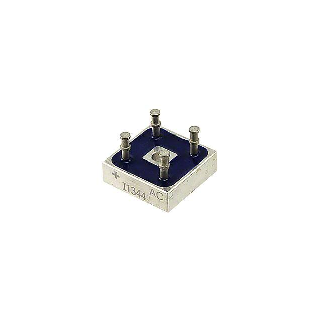


 工商网监
湘ICP备2023018690号
工商网监
湘ICP备2023018690号

