Dual Bootstrapped, 12 V MOSFET
Driver with Output Disable
ADP3110
FEATURES
GENERAL DESCRIPTION
All-in-one synchronous buck driver
Bootstrapped high-side drive
One PWM signal generates both drives
Anticross-conduction protection circuitry
Output disable control turns off both MOSFETs to float
output per Intel® VRM 10 specification
The ADP3110 is a dual, high voltage MOSFET driver optimized
for driving two N-channel MOSFETs, which are the two
switches in a nonisolated synchronous buck power converter.
Each of the drivers is capable of driving a 3000 pF load with a
25 ns propagation delay and a 30 ns transition time. One of the
drivers can be bootstrapped and is designed to handle the high
voltage slew rate associated with floating high-side gate drivers.
The ADP3110 includes overlapping drive protection to prevent
shoot-through current in the external MOSFETs.
APPLICATIONS
Multiphase desktop CPU supplies
Single-supply synchronous buck converters
The OD pin shuts off both the high-side and the low-side
MOSFETs to prevent rapid output capacitor discharge during
system shutdown.
The ADP3110 is specified over the commercial temperature
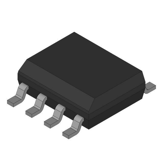
range of 0°C to 85°C and is available in an 8-lead SOIC_N
package.
SIMPLIFIED FUNCTIONAL BLOCK DIAGRAM
12V
D1
VCC
4
BST
ADP3110
1
CBST2
CBST1
IN 2
DRVH
RG
8
Q1
DELAY
RBST
TO
INDUCTOR
SW
7
CMP
VCC
6
CMP
CONTROL
LOGIC
DRVL
Q2
5
PGND
DELAY
6
OD 3
05514-001
1V
Figure 1.
©2010 SCILLC. All rights reserved.
May 2010 – Rev. 2
Publication Order Number:
ADP3110/D
�ADP3110
TABLE OF CONTENTS
Specifications..................................................................................... 3
Overlap Protection Circuit...........................................................7
Absolute Maximum Ratings............................................................ 4
Application Information ...................................................................8
ESD Caution .................................................................................. 4
Supply Capacitor Selection ..........................................................8
Pin Configuration and Function Descriptions ............................. 5
Bootstrap Circuit ...........................................................................8
Timing Characteristics..................................................................... 6
MOSFET Selection ........................................................................8
Theory of Operation ........................................................................ 7
PC Board Layout Considerations................................................9
Low-Side Driver............................................................................ 7
Outline Dimensions ........................................................................11
High-Side Driver .......................................................................... 7
Ordering Guide ...........................................................................11
Rev. 2 | Page 2 of 11 | www.onsemi.com
�ADP3110
SPECIFICATIONS
VCC = 12 V, BST = 4 V to 26 V, TA = 25°C, unless otherwise noted.
Table 1.1
Parameter
Symbol
Conditions
PWM INPUT
Input Voltage High2
Input Voltage Low2
Input Current2
Hysteresis2
Min
Typ
Max
Unit
0.8
+1
V
V
µA
mV
2.0
−1
90
250
OD INPUT
Input Voltage High2
Input Voltage Low2
Input Current 2
Hysteresis2
Propagation Delay Times3
HIGH-SIDE DRIVER
Output Resistance, Sourcing Current
Output Resistance, Sinking Current
Output Resistance, Unbiased
Transition Times
Propagation Delay Times3
SW Pull Down Resistance
LOW-SIDE DRIVER
Output Resistance, Sourcing Current
Output Resistance, Sinking Current
Output Resistance, Unbiased
Transition Times
Propagation Delay Times3
2.0
35
See Figure 3
40
55
ns
BST to SW = 12 V
BST to SW = 12 V
BST to SW = 0 V
BST to SW = 12 V, CLOAD = 3 nF, see Figure 4
BST to SW = 12 V, CLOAD = 3 nF, see Figure 4
BST to SW = 12 V, CLOAD = 3 nF,see Figure 4
BST to SW = 12 V, CLOAD = 3 nF, see Figure 4
SW to PGND
3.8
1.4
10
40
30
45
25
10
4.4
1.8
Ω
Ω
kΩ
ns
ns
ns
ns
kΩ
4.0
1.8
VCC = PGND
CLOAD = 3 nF, see Figure 4
CLOAD = 3 nF, see Figure 4
CLOAD = 3 nF, see Figure 4
CLOAD = 3 nF, see Figure 4
SW = 5 V
SW = PGND
3.4
1.4
10
40
20
15
30
190
150
−1
90
tpdlOD
tpdhOD
RDRV + SW
trDRVH
tfDRVH
tpdhDRVH
tpdlDRVH
RSW − PGND
RDRVL − PGND
trDRVL
tfDRVL
tpdhDRVL
tpdlDRVL
Time-out Delay
SUPPLY
Supply Voltage Range2
Supply Current2
UVLO Voltage2
Hysteresis2
See Figure 3
250
20
V
V
µA
mV
ns
VCC
ISYS
110
95
0.8
+1
4.15
BST = 12 V, IN = 0 V
VCC rising
2
1.5
350
1
All limits at temperature extremes are guaranteed via correlation using standard statistical quality control (SQC) methods.
2
Specifications apply over the full operating temperature range TA = 0°C to 85°C.
3
For propagation delays, tpdh refers to the specified signal going high, and tpdl refers to it going low.
Rev. 2 | Page 3 of 11 | www.onsemi.com
55
45
65
35
50
30
35
40
13.2
5
3.0
Ω
Ω
kΩ
ns
ns
ns
ns
ns
ns
V
mA
V
mV
�ADP3110
ABSOLUTE MAXIMUM RATINGS
Table 2.
Parameter
VCC
BST
BST to SW
SW
DC
很抱歉,暂时无法提供与“ADP3110KRZ-RL-AD”相匹配的价格&库存,您可以联系我们找货
免费人工找货