PA74/PA76
• PA74A/76A
PA74/76
• PA74A/76A
PA74, PA76, PA74A, PA76A
Power Dual Operational Amplifiers
FEATURES
• LOW COST
• WIDE COMMON MODE RANGE —
Includes negative supply
• WIDE SUPPLY VOLTAGE RANGE
Single supply: 5V to 40V
Split supplies: ±2.5V to ±20V
• HIGH EFFICIENCY — |Vs–2.2V| at 2.5A typ
• HIGH OUTPUT CURRENT — 3A
• LOW DISTORTION
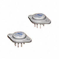
8-PIN TO-3
PACKAGE STYLE CE
APPLICATIONS
R2
+28V 9K
R1
5K
• HALF & FULL BRIDGE MOTOR DRIVERS
• AUDIO POWER AMPLIFIER
STEREO — 30W RMS per channel
BRIDGE — 60W RMS per package
• IDEAL FOR SINGLE SUPPLY SYSTEMS
5V — Peripherals, 12V — Automotive
28V — Avionic
R4
10K
R3
10K
+28V
_
_
M
A
+
COMMAND
INPUT
0/10V
B
1/2 PA74
R5
10K
+
1/2 PA74
R6
10K
FIGURE 1: BIDIRECTIONAL
SPEED CONTROL FROM A
SINGLE SUPPLY.
DESCRIPTION
TYPICAL APPLICATION
The amplifier design consists of dual monolithic input and output
stages to achieve the desired input and output characteristics
of the PA74 and PA76. The input stage utilizes a dual power op
amp on a single chip monolithic that drives the output stages.
The output stages are configured in a non inverting unity gain
buffer configuration. The output stages of the amplifier are also
compensated for stability. The PA74 and PA76 dual amplifiers are
designed with both monolithic and hybrid technologies providing
a cost effective solution for applications requiring multiple amplifiers per board or bridge mode configurations. Both amplifiers
are internally compensated but are not recommended for use
as unity gain followers.
This dual hybrid circuit utilizes a beryllia (BeO) substrate, thick
film resistors, ceramic capacitors and monolithic amplifiers to
maximize reliability and power handling capability, minimize size
and give top performance. Ultrasonically bonded aluminum wires
provide reliable interconnections at all operating temperatures.
The 8-Pin TO-3 package is hermetically sealed and electrically
isolated. The use of compressible isolation washers voids the
warranty.
R1 and R2 set up amplifier A in a non-inverting gain of 2.8.
Amp B is set up as a unity gain inverter driven from the output
of amp A. Note that amp B inverts signals about the reference
node, which is set at mid-supply (14V) by R5 and R6. When
the command input is 5V, the output of amp A is 14V. Since
this is equal to the reference node voltage, the output of amp
B is also 14V, resulting in 0V across the motor. Inputs more
positive than 5V result in motor current flow from left to right
(see Figure 1). Inputs less positive than 5V drive the motor in
the opposite direction.
The amplifiers are especially well-suited for this application.
The extended common mode range allows command inputs
as low as 0V. Its superior output swing abilities let it drive
within 2V of supply at an output current of 2A. This means
that a command input that ranges from 0.714V to 9.286V will
drive a 24V motor from full scale CCW to full scale CW at up
to ±2A. A single power op amp with an output swing capability
of Vs –6 would require ±30V supplies and would be required to
swing 48V p-p at twice the speed to deliver an equivalent drive.
EQUIVALENT SCHEMATIC ONE CHANNEL
EXTERNAL CONNECTIONS
PA74
I BIAS
MONITOR
OUT,B
CURRENT
GAIN
-IN
PA76
-VS
+VS
+IN
THERMAL
PROTECT
8
OUT
CURRENT
GAIN
B
TOP
VIEW
A
1
OUT,A
-VS
www.apexanalog.com
PA74-76U
+VS
+IN,B
–IN,B
7
6
–
+
4
–
Copyright © Apex Microtechnology, Inc. 2012
(All Rights Reserved)
3
-IN,A
+IN,A
6
8
5
+
2
+IN,B
–VS
7
-IN,B
TOP
VIEW
–
B
+
+
1
OUT,B
+VS
2
OUT,A
5
A
–
3
4
-IN,A
+IN,A
OCT 2012
1
PA74-76U REVH
�PA74/76 • PA74A/76A
ABSOLUTE MAXIMUM RATINGS
SUPPLY VOLTAGE, total
OUTPUT CURRENT
POWER DISSIPATION, internal (per amplifier)
POWER DISSIPATION, internal (both amplifiers)
INPUT VOLTAGE, differential
INPUT VOLTAGE, common mode
JUNCTION TEMPERATURE, max1
TEMPERATURE, pin solder–10 sec max
TEMPERATURE RANGE, storage
OPERATING TEMPERATURE RANGE, case
5V to 40V
SOA
36W
60W
±VS
+VS, -VS–0.5V
150°C
350°C
–65°C to 150°C
–55°C to 125°C
SPECIFICATIONS
TEST CONDITIONS2
PARAMETER
INPUT
OFFSET VOLTAGE, initial
OFFSET VOLTAGE, vs. temperature
BIAS CURRENT, initial
COMMON MODE RANGE
COMMON MODE REJECTION, DC
POWER SUPPLY REJECTION
CHANNEL SEPARATION
INPUT NOISE VOLTAGE
GAIN
OPEN LOOP GAIN
GAIN BANDWIDTH PRODUCT
POWER BANDWIDTH
OUTPUT
CURRENT, peak
SLEW RATE
VOLTAGE SWING
VOLTAGE SWING
VOLTAGE SWING
VOLTAGE SWING
MIN
Full temperature range
Full temperature range
Full temperature range
Full temperature range
IOUT = 1A, F = 1kHz
RS = 100Ω, f = 1 to 100KHz
–VS
60
60
50
Full temperature range
AV = 40dB
VO(P-P) = 28V
89
0.9
Full temp. range, IO = 100mA
Full temp. range, IO = 1A
IO = 2.5A (PA74, 76)
IO = 3.0A (PA74A, PA76A)
2.5
0.5
|VS| –1.1
|VS| –2.0
|VS| –3.5
POWER SUPPLY
VOLTAGE, VSS3
CURRENT, quiescent, total
THERMAL
RESISTANCE, junction to case
DC, single amplifier
DC, both amplifiers4
AC, single amplifier
AC, both amplifiers4
RESISTANCE, junction to air
TEMPERATURE RANGE, case
Meets full range specifications
–25
PA74/76
TYP
1.5
20
100
70
90
70
100
1.4
13.6
1.4
|VS| –0.9
|VS| –1.7
|VS| –2.9
PA74A/PA76A
MAX
MIN
TYP
MAX
UNITS
10
.5
7
10
500
*
250
+VS–1.3
*
*
*
*
*
*
*
*
mV
µV/°C
nA
V
dB
dB
dB
*
*
*
*
*
*
dB
MHz
kHz
3
*
*
*
*
*
*
*
*
|VS| –4.0 |VS| –3.3
A
V/µs
V
V
V
V
30
18
40
*
40
*
*
3.2
1.9
2.4
1.4
30
3.5
*
2.1
*
2.6
*
1.6
*
*
85
–25
*
*
V
mA
*
*
*
*
*
85
°C/W
°C/W
°C/W
°C/W
°C/W
°C
NOTES: * The specification of PA74A/PA76A is identical to the specification for PA74/PA76 in applicable column to the left.
1. Long term operation at the maximum junction temperature will result in reduced product life. Derate internal power dissipation to
achieve high MTTF.
2. Unless otherwise noted, the following conditions apply: ±VS = ±15V, TC = 25°C.
3. +VS and –VS denote the positive and negative supply rail respectively. VSS denotes the total rail-to-rail supply voltage.
4. Rating applies when power dissipation is equal in the two amplifiers.
CAUTION
2
The internal substrate contains beryllia (BeO). Do not break the seal. If accidentally broken, do not crush, machine, or
subject to temperatures in excess of 850°C to avoid generating toxic fumes.
PA74-76U
�1.4
1.2
1.0
0.8
0.6
0.4
-80
-20
20
60
100 140
CASE TEMPERATURE, TC (°C)
PULSE RESPONSE
OUTPUT VOLTAGE, VO (V)
15
5
0
80
60 70
0.7
0.6
0.5
0.4
0
5
10
15
SUPPLY VOLTAGE, VS (V)
20
PULSE RESPONSE
10
5
0
+VS = +15V
AV = +1
VIN = 10Vp
-VS = -15V
-10
RL = 10Ω
f = 1KHz
-15 IN
0 200 400 600 800 1.0K 1.2K 1.4K
TIME, t (s)
-5
60
GAIN, A (dB)
PHASE, Ф (°)
0.8
80
120
160
200
240
PA74-76U
0.9
VOLTAGE GAIN vs. FREQUENCY
PHASE vs. FREQUENCY
280
1K
1.0
15
10
+VS = +15V
AV = +1
-5
VIN = 10Vp
-V = -15V
-10 R S= 10Ω
L
fIN = 20KHz
-15
0 10 20 30 40 50
TIME, t (s)
1.1
40
20
0
-20
10K
100K
1M
FREQUENCY, f (Hz)
10M
-40
1K
10K
100K
1M
FREQUENCY, f (Hz)
10M
VOLTAGE DROP FROM SUPPLY, VDROP (V)
1.5
1.2
4.0
OUTPUT VOLTAGE SWING
3.5
3.0
2.5
2.0
1.5
1.0
0.5
0.0
0.0 0.5 1.0 1.5 2.0 2.5 3.0 3.5
OUTPUT CURRENT, IO (A)
NORMALIZED BIAS CURRENT, IB (X)
1.8
NORMALIZED QUIESCENT CURRENT
vs. SUPPLY VOTAGE
1.3
NORMALIZED OFFSET VOLTAGE, VOS (X)
2.0
OUTPUT VOLTAGE, VO (V)
NORMALIZED QUIESCENT CURRENT, IQ (X)
NORMALIZED QUIESCENT CURRENT
vs. CASE TEMPERATURE
NORMALIZED QUIESCENT CURRENT, IQ (X)
PA74/76 • PA74A/76A
8
IB
1.2
1.1
1.0
0.9
0.8
0.7
0.6
-80
-40
0
40 80 120 160
TEMPERATURE, (°C)
VOS
4
0
-4
-40
0
40
80
120
TEMPERATURE, (°C)
3
�PA74/76 • PA74A/76A
GENERAL
Please read Application Note 1 "General Operating Considerations" which covers stability, supplies, heatsinking, mounting,
SOA interpretation, and specification interpretation. Visit www.
apexanalog.com for design tools that help automate tasks such
as calculations for stability, internal power dissipation, heatsink
selection; Apex Microtechnology's complete Application Notes
library; Technical Seminar Workbook; and Evaluation Kits.
PARALLEL CONFIGURATION CONSIDERATIONS
LOSSES
The PA74 and PA76 utilize a parallel configuration to achieve
the desired current output requirements.The parallel configuration inherently creates internal losses due to circulating currents.
The circulating currents generate power losses through the
current sharing resistors when delivering current to the load.
SUPPLY CURRENT
STABILITY CONSIDERATIONS
All monolithic power op amps use output stage topologies
that present special stability problems. This is primarily due to
non-complementary (both devices are NPN) output stages with
a mismatch in gain and phase response for different polarities
of output current. It is difficult for the opamp manufacturer to
optimize compensation for all operating conditions.
The parallel configuration used in the PA74 and PA76 also
generates supply currents while high voltage sign waves are
seen at the output. Listed below are the supply currents expected
while running at a particular frequency and when VO ≈ 15Vpp,
note that the outputs are not loaded.
Frequency
100Hz
1KHz
5KHz
10KHz
15KHz
TWO AMPLIFIERS LOADED
DC, TC = 25°C
SATURATION OPERATION
ONE AMPLIFIER
LOADED
The parallel configuration used in the PA74 and PA76 is
sensitive to operation in the saturation region. The PA74 and
PA76 may exhibit large peak currents; this is mainly due to
thermal protection limitations.
1.0
DC, TC = 85°C
0.1
1.0
10
100
SUPPLY TO OUTPUT DIFFERENTIAL VOLTAGE, VS - VO (V)
SAFE OPERATING AREA (SOA)
The SOA curves combine the effect of all limits for this power
op amp. For a given application, the direction and magnitude
of the output current should be calculated or measured and
checked against the SOA curves. This is simple for resistive
loads but more complex for reactive and EMF generating loads.
THERMAL CONSIDERATIONS
Thermal grease or a Apex Microtechnology TW03 thermal
washer, RCS = .1 to .2°C/W, is the only recommended interface
for the PA74/76. Internal power dissipation increases directly
with frequency therefore it is critical to sufficiently heat sink
the PA74 and PA76. Even unloaded the PA74 and PA76 can
dissipate up to 3 watts while running at higher frequencies.
4
INTERNAL POWER DISSIPATION, P (W)
OUTPUT CURRENT FROM +VS or -VS, (A)
SOA
10
Supply Current
18mA
20mA
32mA
50mA
75mA
POWER DERATING
70
TWO AMPLIFIERS LOADED
60
50
40
ONE AMPLIFIER LOADED
30
20
10
0
0
25
50
75
100
CASE TEMPERATURE, TC (°C)
125
PA74-76U
�PA74/76 • PA74A/76A
NEED TECHNICAL HELP? CONTACT APEX SUPPORT!
For all Apex Microtechnology product questions and inquiries, call toll free 800-546-2739 in North America.
For inquiries via email, please contact apex.support@apexanalog.com.
International customers can also request support by contacting their local Apex Microtechnology Sales Representative.
To find the one nearest to you, go to www.apexanalog.com
IMPORTANT NOTICE
Apex Microtechnology, Inc. has made every effort to insure the accuracy of the content contained in this document. However, the information is subject to change
without notice and is provided "AS IS" without warranty of any kind (expressed or implied). Apex Microtechnology reserves the right to make changes without further
notice to any specifications or products mentioned herein to improve reliability. This document is the property of Apex Microtechnology and by furnishing this information, Apex Microtechnology grants no license, expressed or implied under any patents, mask work rights, copyrights, trademarks, trade secrets or other intellectual
property rights. Apex Microtechnology owns the copyrights associated with the information contained herein and gives consent for copies to be made of the information only for use within your organization with respect to Apex Microtechnology integrated circuits or other products of Apex Microtechnology. This consent does not
extend to other copying such as copying for general distribution, advertising or promotional purposes, or for creating any work for resale.
APEX MICROTECHNOLOGY PRODUCTS ARE NOT DESIGNED, AUTHORIZED OR WARRANTED TO BE SUITABLE FOR USE IN PRODUCTS USED FOR
LIFE SUPPORT, AUTOMOTIVE SAFETY, SECURITY DEVICES, OR OTHER CRITICAL APPLICATIONS. PRODUCTS IN SUCH APPLICATIONS ARE UNDERSTOOD TO BE FULLY AT THE CUSTOMER OR THE CUSTOMER’S RISK.
Apex Microtechnology, Apex and Apex Precision Power are trademarks of Apex Microtechnolgy, Inc. All other corporate names noted herein may be trademarks
of their respective holders.
PA74-76U
www.apexanalog.com
Copyright © Apex Microtechnology, Inc. 2012
(All Rights Reserved)
OCT 2012
5
PA74-76U REVH
�


 工商网监
湘ICP备2023018690号
工商网监
湘ICP备2023018690号
