PRODUCT: Cellular LTE Antenna
Part No. 1002292
PresttaTM Standard Octa-Band
Cellular Embedded Antenna
700/750/850/900/1800/1900/2100/2700 MHz
KEY BENEFITS
DESIGN ADVANTAGES
Ethertronics’ Prestta series of Isolated Magnetic Dipole™ (IMD) embedded antennas address the challenges facing today’s product designers. IMD’s high
performance and isolation characteristics offer better connectivity and minimal interference. Prestta
antennas can be used in a variety of applications including:
M2M
Automotive
Automatic Meter Reading
Healthcare
Point of Sale
Tracking...
TECHNOLOGY ADVANTAGES
Stays in Tune
IMD antenna technology
provides superior RF field
containment, resulting in
less interaction with
surrounding components.
Ethertronics IMD antennas
resist
de-tuning;
providing a robust radio
link regardless of the
usage position.
Prestta antennas use patented IMD technology in a
stamped metal configuration to provide high
performance. IMD antennas requires a smaller design
keep-out area, carry lower program development risk
which yields a quicker time-to-market, without
sacrificing RF performance.
Reduced Costs and Time-to-Market
Standard antenna eliminates design fees and cycle
time associated with a custom solution; getting products to market faster.
Greater Flexibility with Unique Form Factors
Ethertronics’ IMD technology helps you deliver more
advanced ergonomic designs without adverse impact
on product performance.
SMD mountable design enables faster and lower cost
manufacturing.
RoHS Compliant
Ethertronics’ antennas are fully compliant with the
European RoHS Directive 2002/95/EC.
END USER ADVANTAGES
Unique Form Factors Support Advanced
Industrial Designs
Smaller, more efficient IMD embedded antennas break
through restrictive design rules and provide new freedom in component placement.
Superior Range
Better antenna function means longer range and greater sensitivity to critically precise signals—delivering
greater customer satisfaction while building brand loyalty.
SERVICE AND SUPPORT
Extensive RF Experience
Our Prestta antennas are supported by documentation,
and when needed, by the expertise of RF engineers
who have integrated hundreds of antenna designs into
wireless devices.
Global Operations & Design Support
Ethertronics’ global operations supports an integrated
network of design centers that can take projects from
concept to production.
ETHERTRONICS
5501 Oberlin Drive, Suite 100, San Diego, CA. 92121, USA www.ethertronics.com
Tel +(1) 858.550.3820 | fax +(1) 858.550.3821 | contact: info@ethertronics.com
�PRODUCT: Cellular Antenna - P/N 1002292
Ethertronics’ Cellular Internal (Embedded) Antenna Specifications.
Below are the typical performances for a cellular application.
Electrical Specifications
Typical Characteristics. Antenna mounted directly on PC + ABS plastic carrier
Mechanical Specifications
Maximum Dimensions
Cable / Connector
85.2 x 42.1 x 0.15 mm (1.25mm high at cable solder connection)
U.fl compatible connector, Cable diameter 1.13mm, 28.5mm Cable length.
Mounting
Antenna backing using 3M468 Adhesive on FPC substrate
Antenna Configuration 1
Antenna Configuration 2
Antenna located in Free Space
Antenna located at the end of a PCB.
75 mm
In this position, the antenna is located 1 mm away from the PCB
and 5 mm above the PCB.
ETHERTRONICS
5501 Oberlin Drive, Suite 100, San Diego, CA. 92121, USA www.ethertronics.com
Tel +(1) 858.550.3820 | fax +(1) 858.550.3821 | contact: info@ethertronics.com
�PRODUCT: Cellular Antenna - P/N 1002292
Return Loss in dB (Low Band)
Free Space
Over GND Plane
Return Loss, in dB (High Band)
Free Space
Over GND Plane
Typical Low Band Efficiency, 700-960MHz
Free Space
Over GND Plane
Typical High Band Efficiency, 1700-2700MHz
Free Space
Over GND Plane
ETHERTRONICS
5501 Oberlin Drive, Suite 100, San Diego, CA. 92121, USA www.ethertronics.com
Tel +(1) 858.550.3820 | fax +(1) 858.550.3821 | contact: info@ethertronics.com
�PRODUCT: Cellular Antenna - P/N 1002292
Radiation Patterns Setup Conditions
Antenna Configuration 1
Antenna Configuration 2
Antenna located in Free Space
Antenna located at the end of a PCB.
ETHERTRONICS
5501 Oberlin Drive, Suite 100, San Diego, CA. 92121, USA www.ethertronics.com
Tel +(1) 858.550.3820 | fax +(1) 858.550.3821 | contact: info@ethertronics.com
�PRODUCT: Cellular Antenna - P/N 1002292
Typical Radiation Patterns - Antenna Configuration 1 : In Free Space
The Peak gain in the frequency band 700-960MHz is 0.5 dBi.
The Peak gain in the frequency band 1710-2200MHz is 3.0 dBi.
ETHERTRONICS
5501 Oberlin Drive, Suite 100, San Diego, CA. 92121, USA www.ethertronics.com
Tel +(1) 858.550.3820 | fax +(1) 858.550.3821 | contact: info@ethertronics.com
�PRODUCT: Cellular Antenna - P/N 1002292
Typical Radiation Patterns - Antenna Configuration 2 : Over the Ground Plane
The Peak gain in the frequency band 820-960MHz is 3.0 dBi.
The Peak gain in the frequency band 1710-2200MHz is 5.0 dBi.
© 2013 Ethertronics. All rights reserved. Ethertronics, the Ethertronics logo, shaping antenna technology, Prestta, Isolated Magnetic Dipole and the
iMD logo are trademarks of Ethertronics. All other trademarks are the property of their respective owners.
Specifications subject to change and are dependent upon actual implementation.
1002292 01FEB2014
�
很抱歉,暂时无法提供与“1002292”相匹配的价格&库存,您可以联系我们找货
免费人工找货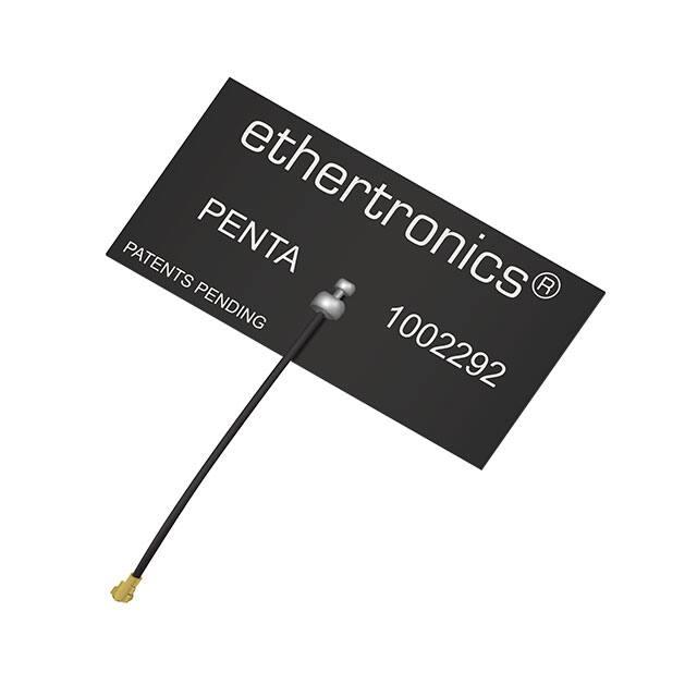


 工商网监
湘ICP备2023018690号
工商网监
湘ICP备2023018690号
