AP8803EV1 EVALUATION BOARD USER GUIDE
DESCRIPTION
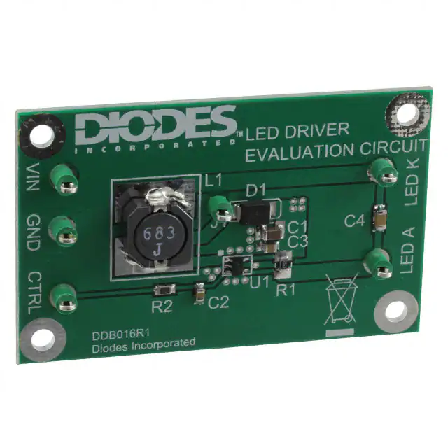
The AP8803EV1, Figure 1, is a double sided evaluation board for the AP8803 LED
driver with internal switch. The evaluation board is preset to drive 680mA into a
single LED, or multiple LEDs, the maximum number of which depends on their total
forward voltage drop.
The operating voltage is nominally 30 volts, but it can be reduced to a minimum of 8
volts. The 68uH inductor used in the circuit is based on this nominal supply, which
should be connected across the +Vin and Gnd pins. Note: The evaluation board
does not have reverse battery protection. The nominal current, 680mA, is set
with the 0R15 sense resistor, R1.
Terminal CTRL provides a connection point for DC or PWM dimming and shutdown.
Warning: At 30V nominal operation with 680mA output, the LED will be hot and very bright
Figure 1: AP8803EV1 evaluation board
Issue 1 – Jan 2010
© Diodes Incorporated, 2008
www.diodes.com
�AP8803EV1
AP8803 DEVICE DESCRIPTION
The AP8803 is a continuous mode inductive driver in a TSOT23-5 package, for driving one or more
series-connected LEDs efficiently from a voltage source higher than the LED voltage. The device
includes the output switch and a current sense circuit, which requires an external sense resistor to set
the nominal current up to 1000mA.
AP8803 DEVICE FEATURES
• Drives one or more series-connected LEDs
• LEDs up to 1000mA.
• Internal 30V switch.
• Wide input voltage: 8V to 30V.
• Inherent open circuit LED protection.
• Brightness control using DC or PWM.
• Internal PWM filter.
DEVICE APPLICATIONS
• LED flashlights.
• High Power LED driving.
• Low-voltage halogen replacement LEDs.
• Automotive lighting.
• Illuminated signs.
AP8803 Device Packages, Pin and Definitions
TSOT23-5 pack
AP8803 Device Pin Definition
Name
Pin No
Description
SW
1
Drain of NDMOS switch.
GND
2
Ground (0V).
CTRL
3
Internal voltage ref. pin (1.25V) :
• Leave floating for normal operation.
• Connect to GND to turn off output current.
• Drive with DC voltage (0.3V to 1.25V) or with PWM signal to
Adjust output current or....
• Connect a capacitor from this pin to ground to set soft-start
time.
SET
4
Connect a sense resistor, Rs, from the CTRL pin to VIN to sense the
nominal output current. Nominal Iout = 0.1/ R1
VIN
5
Input voltage: 8V to 30V. Decouple to ground with a 4.7uF or higher
ceramic capacitor.
ORDERING INFORMATION
EVALBOARD ORDER
NUMBER
AP8803EV1
DEVICE ORDER NUMBER
AP8803E5TA
Please note: Evaluation boards are subject to
availability and qualified sales leads.
Issue 1 – Jan 2010
www.diodes.com
© Diodes Incorporated 2010
2
�AP8803EV1
AP8803EV1 EVALUATION BOARD
REFERENCE DESIGN
The AP8803EV1 is configured to the reference design in Figure 2.
The operating voltage is a nominal 30V. The nominal current is set at 680mA with a 0R15 sense
resistor, R1 and the circuit operates in continuous mode at approximately 180kHz, with a 68uH
inductor and a single LED.
An accurate way of determining the current is to measure the voltage on the sense resistor. A 10K
resistor and a 1uF capacitor can be used to form a low pass filter, the voltage across the capacitor
representing a more stable DC reading of current . 100mV represents 1 Amp when using a 0R1 sense
resistor.
The CTRL pin has a low pass filter within the AP8803 chip to provide some decoupling and a soft
start, but the external capacitor C1 (100nF) is used to provide additional decoupling to reduce any
high frequency noise, as well as providing an extra amount of soft start.
Both DC and PWM dimming can be achieved by driving the CTRL pin. For DC dimming, the CTRL pin
may be driven between 0.3V and 1.25V. Driving the CTRL pin below 0.2V will shutdown the output
current. For PWM dimming, an external open-collector NPN transistor or open-drain N-channel
MOSFET can be used to drive the CTRL pin. The PWM frequency can be low, around 100Hz to 1kHz,
or high, between 10kHz to 50kHz.
For low frequency PWM, C1 should be removed from the evaluation board, to give a more accurate
duty cycle .
Shorting R2 will connect the test pin CTRL to device pin CTRL, if required.
The soft-start time will be nominally 0.5ms without capacitor C1. Adding C1 will increase the soft start
time by approximately 0.5ms/nF
For other reference designs or further applications information, please refer to the AP8803 datasheet.
Schematic Diagram
Issue 1 – Jan 2010
www.diodes.com
© Diodes Incorporated 2010
3
�AP8803EV1
AP8803 Operation
In normal operation, when voltage is applied at +Vin, the AP8803 internal NDMOS switch is turned
on. Current starts to flow through sense resistor R1, inductor L1, and the LED. The current ramps up
linearly, and the ramp rate is determined by the input voltage +Vin and the inductor L1. This rising
current produces a voltage ramp across R1. The internal circuit of the AP8803 senses the voltage
across R1 and applies a proportional voltage to the input of the internal comparator. When this
voltage reaches an internally set upper threshold, the NDMOS switch is turned off. The inductor
current continues to flow through R1, L1, the LED and the schottky diode D1, and back to the supply
rail, but it decays, with the rate of decay determined by the forward voltage drop of the LEDs and the
schottky diode. This decaying current produces a falling voltage at R1, which is sensed by the
AP8803. A voltage proportional to the sense voltage across R1 is applied at the input of the internal
comparator. When this voltage falls to the internally set lower threshold, the NDMOS switch is turned
on again. This switch-on-and-off cycle continues to provide the average LED current set by the sense
resistor R1. Please refer to the datasheets for the threshold limits, AP8803 internal circuits, electrical
characteristics and parameters.
AP8803EV1 Component list
Ref
Value
Package
Part Number
U1
AP8803
TSOT235
AP8803E5TA
D1
40V, 3A
R1
R2,
C1
0R15
1K
4.7uF 50V
0805
0805
1210
C2, C3
100nF, 100V
0805
B340B
C1210X475K5RAC
NMC0805X7R104K100 PF
GRM21BR71H104KA01L
C4
L1
100nF 100V
68uH
1206
NMC1206X7R104K100
MSS1038-683ML
NPIS24H680MTRF
Manufactu
rer
Diodes
Zetex
Diodes
Zetex
Generic
Generic
Generic
KEMET
Generic
NIC Comps
MURATA
Generic
NIC Comps
Coilcraft
NIC Comps
Notes
DC-DC converter
Schottky diode
5%
1%
X7R
X7R
X7R
Note: The component part numbers are correct at the time of publication. Diodes Inc reserves the
right to substitute other parts where necessary, without further notification.
Issue 1 – Jan 2010
www.diodes.com
© Diodes Incorporated 2010
4
�AP8803EV1
Figure 3: Component layout
AP8803EV1 Connection Point Definition
Name
Description
Vin
Positive supply voltage.
Gnd
Supply Ground (0V).
CTRL
LED A
LED K
Internal voltage ref. pin (1.25). This pin can be used to achieve dimming and
soft-start, and for switching the output current off.
• Leave floating for normal operation.
• See 'Other Features' section to achieve dimming, and soft-start and for
switching the output current off.
LED A connects to the external LED anode
LED K connects to the external LED cathode
AP8803EV1 Basic operation at full voltage
1. Connect Vin and Gnd
Warning: The board does not feature reverse battery/supply protection.
2. Set the PSU to 30V
3. Turn on the PSU and the LED will illuminate and the current should be approximately 680mA.
Warning: Do not stare at the LED directly.
Issue 1 – Jan 2010
www.diodes.com
© Diodes Incorporated 2010
5
�AP8803EV1
Circuit features (Remove power whilst changing components!)
Soft-start
1. Fit a capacitor at C2 to alter the rise-time of the CTRL pin at start-up. The output impedance
is 200k so
200,000R x C2 (farads) is the time constant to reach 66% of the maximum output current
Switching the output current off
1. Shorting the CTRL pin to Gnd will cause the LED current to go to zero. Releasing this pin will
create a soft-start power-up sequence.
Changing the LED current
1. Remove R1.
2. Calculate and fit a new sense resistor, R1, the value of which is based on the required LED
current without dimming. R1 can be calculated using following equation :
R1 = 0.1V/IOUT where IOUT = the LED current.
R1 = the sense resistor value in ohms.
0.1V is the nominal sense voltage with ‘CTRL’ open circuit or set to
1.25V.
PERFORMANCE
The system efficiency depends on the sense resistor, supply voltage, switching inductor and the
number of LEDs.
With a 30V supply, the switching frequency is typically 200kHz, and the efficiency level is >85% .
Issue 1 – Jan 2010
www.diodes.com
© Diodes Incorporated 2010
6
�AP8803EV1
INTENTIONALLY BLANK
Issue 1 – Jan 2010
www.diodes.com
© Diodes Incorporated 2010
7
�AP8803EV1
IMPORTANT NOTICE
DIODES INCORPORATED MAKES NO WARRANTY OF ANY KIND, EXPRESS OR IMPLIED, WITH REGARD TO THIS
DOCUMENT, INCLUDING, BUT NOT LIMITED TO, THE IMPLIED WARRANTIES OF MERCHANTABILITY AND
FITNESS FOR A PARTICULAR PURPOSE (AND THEIR EQUIVALENTS UNDER THE LAWS OF ANY JURISDICTION).
Diodes Incorporated and its subsidiaries reserve the right to make modifications, enhancements, improvements,
corrections or other changes without further notice to this document and any product described herein. Diodes Incorporated
does not assume any liability arising out of the application or use of this document or any product described herein; neither
does Diodes Incorporated convey any license under its patent or trademark rights, nor the rights of others. Any Customer
or user of this document or products described herein in such applications shall assume all risks of such use and will agree
to hold Diodes Incorporated and all the companies whose products are represented on Diodes Incorporated website,
harmless against all damages.
Diodes Incorporated does not warrant or accept any liability whatsoever in respect of any products purchased through
unauthorized sales channels. Should Customers purchase or use Diodes Incorporated products for any unintended or
unauthorized application, Customers shall indemnify and hold Diodes Incorporated and its representatives harmless
against all claims, damages, expenses, and attorney fees arising out of, directly or indirectly, any claim of personal injury or
death associated with such unintended or unauthorized application.
Products described herein may be covered by one or more United States, international or foreign patents pending. Product
names and markings noted herein may also be covered by one or more United States, international or foreign trademarks.
LIFE SUPPORT
Diodes Incorporated products are specifically not authorized for use as critical components in life support devices or
systems without the express written approval of the Chief Executive Officer of Diodes Incorporated. As used herein:
A. Life support devices or systems are devices or systems which:
1. are intended to implant into the body, or
2. support or sustain life and whose failure to perform when properly used in accordance with instructions for use
provided in the labeling can be reasonably expected to result in significant injury to the user.
B. A critical component is any component in a life support device or system whose failure to perform can be reasonably
be expected to cause the failure of the life support device or to affect its safety or effectiveness.
Customers represent that they have all necessary expertise in the safety and regulatory ramifications of their life support
devices or systems, and acknowledge and agree that they are solely responsible for all legal, regulatory and safety-related
requirements concerning their products and any use of Diodes Incorporated products in such safety-critical, life support
devices or systems, notwithstanding any devices- or systems-related information or support that may be provided by
Diodes Incorporated. Further, Customers must fully indemnify Diodes Incorporated and its representatives against any
damages arising out of the use of Diodes Incorporated products in such safety-critical, life support devices or systems.
Copyright © 2009, Diodes Incorporated
www.diodes.com
Sales offices
The Americas
Europe
Taiwan
Shanghai
Shenzhen
Korea
3050 E. Hillcrest Drive
Westlake Village,
CA 91362-3154
Kustermannpark
Balanstraße 59,
D-81541 München
7F, No. 50,
Min Chuan Road
Hsin-Tien
Rm. 606, No.1158
Changning Road
Shanghai, China
Room A1103-04,
ANLIAN Plaza, #4018
Jintian Road
6 Floor, Changhwa B/D,
1005-5 Yeongtong-dong,
Yeongtong-gu, Suwon-si,
Tel: (+1) 805 446 4800
Fax: (+1) 805 446 4850
Germany
Tel: (+49) 894 549 490
Fax: (+49) 894 549 4949
Taipei, Taiwan
Tel: (+886) 289 146 000
Fax: (+886) 289 146 639
Tel: (+86) 215 241 4882
Fax (+86) 215 241 4891
Futian CBD,
Shenzhen, China
Tel: (+86) 755 882 849 88
Fax: (+86) 755 882 849 99
Gyeonggi-do, Korea 443-813
Tel: (+82) 312 731 884
Fax: (+82) 312 731 885
Issue 1 – Jan 2010
www.diodes.com
© Diodes Incorporated 2010
8
�


 工商网监
湘ICP备2023018690号
工商网监
湘ICP备2023018690号
