bq78412
www.ti.com
SLUSAA0 – OCTOBER 2010
bq78412 Pb-Acid Battery State-of-Charge Indicator With Run-Time Display
Check for Samples: bq78412
FEATURES
DESCRIPTION
•
The bq78412 Pb-Acid Battery State-of-Charge (SoC)
Indicator with Run-Time Display is a complete
stand-alone battery gas-gauge solution designed for
single 12V Pb-Acid batteries. The bq78412 displays
remaining Run-Time-To-Empty during discharge and
Percent (%) capacity during charge using a 10-LED
(light-emitting diode) bar graph.
1
•
•
•
•
•
•
•
•
•
•
•
•
Designed for Use with 12-V Lead-Acid
Batteries in Consumer UPS Systems
Programmable Cell Models for Enhanced
Pb-Acid Gas Gauging Performance
Provides 10-LED Bar Graph of Run-Time
Remaining During Discharge and % Capacity
During Charge
Can Be Easily Integrated Into Battery Cover
Works with Pb-Acid Batteries Up to 327 Ah
Records Cumulative Usage Data Internally for
Warranty Return Analysis
On-Chip Temperature Sensor
Data Interface for Retrieving Warranty
Information
Fully Programmable Features and Thresholds
via UART Serial Interface
State-of-Health (SoH) Determination and
Status Reporting
Includes Configurable Signal for Audible
Low-Capacity, Low-Voltage, and Overvoltage
Warnings
Addressable Commands for Use in
Multi-Battery Systems
Optional Infra-Red Communications Interface
APPLICATIONS
•
•
•
Stand-Alone Uninterruptible Power Supplies
12-V Pb-Acid Battery Monitors
Battery Warranty Data Logging Equipment
The bq78412 monitors battery voltage, current, and
ambient temperature to calculate state-of-charge and
determine remaining runtime-to-empty. Measured
values can be recorded and tracked for later retrieval
for warranty purposes.
Programmable cell models allow the bq78412 to be
customized to a variety of Pb-Acid formulations and
capacities.
Current measurements and Coulomb-counting for
gas-gauging are also automatically performed by the
bq78412. Current measurements use a small value
sense resistor placed in the negative power path and
calibrated in-circuit. This allows the precise,
continuous, real-time calculation of battery capacity
and run-time-to-empty values.
Temperature sensing augments gas-gauge and
capacity information using a firmware algorithm to
compensate for the temperature effects on capacity.
A serial port is available for configuring various
programmable parameters including cell models,
calibration values, serial number and date of
manufacture. The serial port can operate an infra-red
(IR) interface to allow connector-less data acquisition.
The bq78412 is easily configurable, is fully
programmed and requires no algorithm or firmware
development
1
Please be aware that an important notice concerning availability, standard warranty, and use in critical applications of Texas
Instruments semiconductor products and disclaimers thereto appears at the end of this data sheet.
PRODUCTION DATA information is current as of publication date.
Products conform to specifications per the terms of the Texas
Instruments standard warranty. Production processing does not
necessarily include testing of all parameters.
Copyright © 2010, Texas Instruments Incorporated
�bq78412
SLUSAA0 – OCTOBER 2010
www.ti.com
These devices have limited built-in ESD protection. The leads should be shorted together or the device placed in conductive foam
during storage or handling to prevent electrostatic damage to the MOS gates.
ABSOLUTE MAXIMUM RATINGS (1)
VALUE
PARAMETER
MIN
MAX
Voltage applied to VBAT+
–0.3
30
Voltage applied to VS
Voltage applied to
RS+, RS–
UNITS
V
–0.3
26
V
Differential (VRS+– VRS–)
–26
26
V
Common mode (VRS+, VRS–)
–0.3
26
V
Voltage applied to AVDD and DVDD
–0.3
4.1
V
Voltage applied to other pins (2)
–0.3
VVDD+0.3
V
–2
2
Diode current at any device terminal
(1)
(2)
mA
Stresses above these ratings may cause permanent damage. Exposure to absolute maximum conditions for extended periods may
degrade device reliability. These are stress ratings only, and functional operation of the device at these or any other conditions beyond
those specified is not implied.
VDD refers to voltage on DVDD and AVDD pins.
RECOMMENDED OPERATING CONDITIONS
Supply voltage
VBAT+
Operating temperature
MIN
TYP
MAX
4
12
26
85
°C
150
327
Ahr
–40
Battery capacity
UNITS
V
Current measurement, average
–100
100
A
Current measurement, peak
–320
300
A
MEASUREMENT ACCURACY (12-V Battery)
PARAMETER
TYP
MAX
Battery voltage measurement (1)
±0.5%
±1%
Shunt voltage measurement (2)
±0.5%
±1%
Temperature measurement
MIN
(3)
±1
Timing accuracy of internal clock (4)
–2.5%
Run-time-to-empty (RTTE) (5)
(1)
(2)
(3)
(4)
(5)
UNIT
°C
2.5%
±15
min
Specified at 12 V.
Specified at full scale.
Offset calibration of the temperature takes place prior to this measurement
Calibrated clock frequency, tolerance over temperature 0°C to +85°C
Capacity learning is done prior to this.
UART COMMUNICATIONS PORT TIMING
MIN
Data rate
Transmit intercharacter interval (2)
2
MAX
9600 or
1200
Command response time (1)
(1)
(2)
TYP
UNITS
Baud
100
ms
4
ms
Maximum time from host transmission of last command byte to first response by the device.
Maximum time interval between start bits for data or response being transmitted from the device.
Submit Documentation Feedback
Copyright © 2010, Texas Instruments Incorporated
Product Folder Link(s): bq78412
�bq78412
www.ti.com
SLUSAA0 – OCTOBER 2010
CURRENT CONSUMPTION
OPERATING MODE
TYPICAL (mA)
NOTES
Active
3.2
Connected to UPS and gas gauging active. Display is active and not included.
Idle
3.2
Not connected to UPS. Display is active and not included.
Sleep
3.2
Not connected. Display off.
ELECTRICAL CHARACTERISTICS
PARAMETER
CONDITIONS
MIN
100 µA ≤ ILOAD ≤ 100 mA, TJ = 25°C
REG33 load regulation
TYP
MAX
0.04%
0.20%
100 µA ≤ ILOAD ≤ 100 mA, –40°C ≤ TJ ≤ 85°C
UNIT
0.30%
ADC basic resolution
Sense voltage measurement step size
Shunt current measurement step size
12
bits
4
mV
0.1
Full scale current sense voltage range
Sense resistor
A
±160
mV
1
mΩ
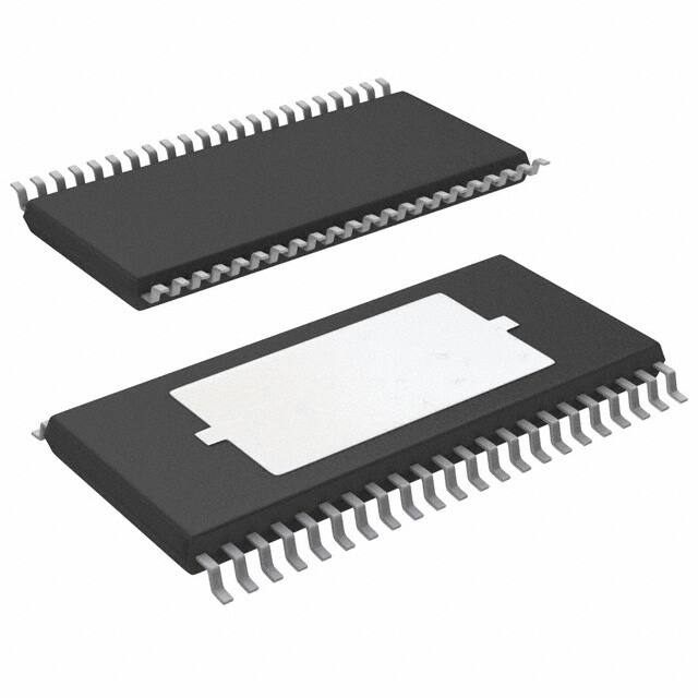
Package Outline
DDW Package
(Top View)
N/C
SCLK
SDAT
N/C
SDA
SCL
SD
TXD
RXD
BUZZER
N/C
N/C
N/C
AVDD
AVSS
VS
RS–
RS+
N/C
N/C
A0
A1
1
44
2
43
3
42
4
41
5
40
6
39
7
38
8
37
9
36
10
35
11
34
12
33
13
32
14
31
15
30
16
29
17
28
18
27
19
26
20
25
21
24
22
23
A.
Thermal pad is on the bottom side of the package
B.
N/C = no connect
RST_N
XIN
XOUT
DVSS
RSVD
DVDD
TEST5
TEST4
TEST3
TEST2
TEST1
N/C
DISPEN
RSVD
N/C
AVSS
REG33
N/C
N/C
VBAT+
SCL
SDA
Submit Documentation Feedback
Copyright © 2010, Texas Instruments Incorporated
Product Folder Link(s): bq78412
3
�bq78412
SLUSAA0 – OCTOBER 2010
www.ti.com
PIN DESCRIPTIONS
bq78412
I/O/P
DESCRIPTION
NAME
No.
A0
21
I
Configuration input. Connect to ground.
A1
22
I
Configuration input. Connect to ground.
AVDD
14
P
3.3-V power to the analog logic. Typically connected to REG33.
P
Connect to ground.
15
AVSS
29
BUZZER
10
O
Buzzer output. Active high when alarm condition is detected.
DISPEN
32
O
Active high output, turns on display enable transistor. Not required in all applications. Blanks display during
updates.
DVDD
39
P
3.3-V supply to the digital logic. Connect a 2.2- µF capacitor to VSS. Typically connected to REG33.
DVSS
41
P
Connect to ground
REG33
28
P
Regulated 3.3-V power output.
RST_N
44
I
Connect to external RC network for power-up reset.
–
Reserved, no connection required.
RSVD
31
40
RS–
17
I
Current sense negative
RS+
18
I
Current sense positive
RXD
9
I
UART RX data
6
O
I2C clock output
24
I
I2C clock for internal use. Connect to SCL pin 6.
SCLK
2
O
Low-to-high transition clocks data into external serial in, parallel out shift register.
SD
7
O
IR XCVR Shutdown; HIGH=XCVR in shutdown, LOW=XCVR Active
5
I/O
I2C data
23
I/O
I2C data for internal use. Connect to SDA pin 5.
SCL
SDA
SDAT
3
O
Serial display data to serial in, parallel out shift register. A low bit turns on an LED.
TEST1
34
I/O
Test pin, no connection
TEST2
35
I/O
Test pin, no connection
TEST3
36
I/O
Test pin, no connection
TEST4
37
I/O
Test pin, no connection
TEST5
38
I/O
Test pin, no connection
TXD
8
O
UART TX data
VBAT+
25
P
Input to internal regulator.
VS
16
I
Sense voltage. Connect to battery positive.
XIN
43
I
Input terminal of 8-MHz crystal oscillator or crystal pin. (Optional: Can be left unconnected to use internal
oscillator)
XOUT
42
O
Output terminal of 8-MHz crystal oscillator or crystal pin. (Optional: Can be left unconnected to use internal
oscillator)
–
No connection
1
4
11
12
N/C
13
19
20
26
27
33
4
Submit Documentation Feedback
Copyright © 2010, Texas Instruments Incorporated
Product Folder Link(s): bq78412
�bq78412
www.ti.com
SLUSAA0 – OCTOBER 2010
TYPICAL APPLICATION
+
3.3 kW
3.3 kW
VCC
39
10 mF
50 V
2.2 mF
28
100 W
DVDD
REG33
bq78412DDW
VBAT+ 25
VCC
SDA 23
5
SDA
6
SCL
1 kW
+
SCL 24
A1 22
A0 21
10 W
RS+ 18
10 kW
MMBT
3904
10 BUZZER
CF (1)
RS– 17
37 TEST4
GP2W0116YPS
36 TEST3
47 kW
AVSS 15
34 TEST1
LEDA
6
TXD
5
8
TXD
RXD
4
9
RXD
SD
3
7
SD
AVDD 14
SN74HC164
DISPEN 32
SDAT
3
SCLK
2
N/C
1
2
N/C 12
1
4
7
1 W to 15 W
1 mF
6.3 V
N/C
SCLK
1
A
Q0
3
2
B
Q1
4
8
CLK
Q2
5
9
CLR
Q3
6
14 VCC
Q4 10
7
Q5 11
GND
N/C 13
19 N/C
N/C 30
20 N/C
N/C 33
Q6 12
Q7 13
GRN
LED9
GRN
LED8
GRN
LED7
GRN
LED6
YEL
LED5
YEL
LED4
YEL
LED3
RED
LED2
RED
LED1
RED
LED0
RED
Replace
YEL
Warn
GRN
Good
GRN
Charge
GRN
Discharge
GRN
Full
26 N/C
27 N/C
RSVD 31
RSVD 40
47 kW
44 RST_N
0.001 mF
6.3 V
SDAT
MMBT
3904
470 W (x 16)
RTTE Status / %SoC
N/C 11
SGND
MMBT
3904
10 kW
35 TEST2
VCC
RS
1 mW/2W
10 W
VS 16
38 TEST5
GND
12-V
Pb-Acid
Battery
SN74HC164
A
Q0
3
2
B
Q1
4
XOUT 42
DVSS
AVSS
8
CLK
Q2
5
41
29
9
CLR
Q3
6
14 VCC
Q4 10
Q5 11
7
GND
Q7 13
Mode
Q6 12
SoH Status
1
XIN 43
_
UDG-10084
(1)
CF = 0.1 µF to 1 µF
Submit Documentation Feedback
Copyright © 2010, Texas Instruments Incorporated
Product Folder Link(s): bq78412
5
�bq78412
SLUSAA0 – OCTOBER 2010
www.ti.com
APPLICATION INFORMATION
Overview
The bq78412 is a complete Pb-Acid gas-gauge with a run-time display and warranty information storage. It
supports large batteries up to a maximum capacity of 327 Ahr when measured at the 20 hour rate.
Measurement inputs include the 12-V nominal battery voltage and the battery current. Coulomb counting on
discharge and charge allows a state-of-charge calculation and run-time-to-empty on discharge estimation.
Cumulative usage information is periodically and permanently stored internally and may be retrieved only by a
special sequencing operation performed by the manufacturer.
Operation of the bq78412 requires no user interaction. During charge and discharge, the LED display is
automatically activated when charge or discharge current is detected above a configurable threshold.
Current Sense, Battery Voltage, Temperature, and Time Measurements
The bq78412 measures charge and discharge current using a low-value (between 1 and 3 mΩ) sense resistor
placed in the negative power path of the circuit. This sense resistor may be as simple as a piece of thermally
stable metal or the lead power post on the battery itself. Calibration of this sense resistor is required in circuit (in
module). The printed circuit board (PCB) designer must consider the impact of drift and/or variation in the sense
resistor value over time and temperature, including self-heating temperature effects. The bq78412 does not
compensate for such changes.
The voltage measured between the RS+ and RS– pins is scaled by the sense resistor value (set in MeasScale
parameter) to calculate the current value. The maximum differential voltage allowed between the RS+ pin and
the RS– pin is 160 mV.
Alternatively, a voltage proportional to the current (derived using means other than a sense resistor, but within
range of the allowable differential) could be applied to the terminals to provide the current measurement.
The bq78412 measures the battery voltage between the VS and AVSS pins
The bq78412 has an on-chip temperature sensor. The battery temperature is assumed to be equal to the on-chip
measurement.
Time measurement is referenced to an internal oscillator. However, for more accuracy, an external 8-MHz crystal
oscillator or crystal can be used. This is enabled by setting DevConfig2[15] = 1. The switch-over happens only
after a hardware or software reset.
State-of-Charge (SoC) Gas-Gauging
The bq78412 provides capacity and run-time-to-empty estimates for Pb-Acid batteries using a rate and
temperature compensated coulomb counting algorithm.
The gas-gauging information is used to drive the local LED display with run-time-to-empty information.
Capacity correction is supported based on the discharge current. A 64-byte battery characterization table
contains battery performance data that is used to adjust the remaining capacity and run-time-to-empty as a
function of discharge rate and temperature. This information is unique to each battery model and is programmed
at the battery manufacturing facility based on battery performance data provided by the manufacturer.
Charge Efficiency Compensation
The bq78412 provides a parameter, ChgEff that allows for correction of accumulated charge in the battery due to
charge efficiency. During charge, the passed charge is multiplied by the charge efficiency and the result is added
to the remaining capacity.
For example, if ChgEff is set to 85 (representing 85%), when 100 Ah have been measured, only 85 Ah are
recorded as actually being accumulated. With the default setting for the ChgEff = 100, all charge current is
accumulated.
6
Submit Documentation Feedback
Copyright © 2010, Texas Instruments Incorporated
Product Folder Link(s): bq78412
�bq78412
www.ti.com
SLUSAA0 – OCTOBER 2010
Gas Gauging After a Reset
During normal operation, the last learned full charge capacity (FCC), elapsed time and other important variables
are stored in permanent memory. If, for some reason the battery discharges to the point where there is no longer
sufficient voltage for the bq78412 to operate, it shuts down. Under such conditions, when the device powers up,
these variables are restored and battery is assumed to be at 50% relative SoC. If a charge current is present, the
device begins to measure the accumulated charge and time. Charging proceeds as normal with the appropriate
end-of-charge detection criteria. If the bq78412 powers up and there is no current, the device goes into idle state
followed by sleep state until a current is detected.
Battery Capacity Update
The bq78412 has two mechanisms for updating the battery capacity as the battery ages. (Note that the initial
capacity programmed into the bq78412 could be in error due to manufacturing tolerances or formation
procedures. This translates to a gas gauging error until the battery capacity is accurately learned.)
Both the Learned Capacity method and Age-Based Capacity method operate independently and both may be
enabled or disabled separately in order to maintain the correct measure of capacity of the battery over a variety
of operating conditions, but it is suggested that both be enabled for optimal performance.
Learned Capacity Method
When DevConfig1[14] is set to "1", the bq78412 opportunistically learns the full charge capacity (FCC) of the
battery based on a qualified discharge. A complete discharge from fully charged to fully discharged with no
charging events raising the remaining state of charge (SoC) above 80% is considered qualified. An internal state
variable qualified discharge (QD) is used for maintaining the status of discharge qualification. QD is initially
disabled. When the battery has reached the fully charged state, QD is set to enabled and discharge learn
accumulator is cleared to zero. When a discharge begins, QD is set to active. While QD is active, all passed
charge (positive or negative) is accumulated in the discharge learn accumulator. If at any time (while QD is in an
active state) a charging event raises SoC above 80%, QD is set to disabled and the discharge learn accumulator
is ignored. If the battery reaches the fully discharged state and QD is still active, the algorithm learns FCC based
on the discharge learn accumulator and the current load de-rating using Equation 1.
Discharge Learn Accumulator
FCC =
Derating
where
•
Derating is the capacity derating fraction as a function of load current
(1)
Age-Based Capacity Method
The counter for the elapsed time starts when the device is activated.
When DevConfig1[15] is set to "1" (non-default), the bq78412 updates the FCC based on elapsed time and an
aging algorithm with manufacturer defined parameters. The bq78412 decrements the FCC by 0.100 Ah every
CapDerateL days until DerateChange days have elapsed, after which the FCC decrements by the same amount
every CapDerateH days.
In this way the FCC is regularly de-rated (decremented) at regular intervals independently of the learned capacity
method.
The values for CapDerateL, DerateChange, and CapDerateH must be carefully chosen to implement an
appropriate age-based capacity decrease formula.
For example: Assuming a 100Ah battery (when new) and a 3%/year capacity fade for the first 3 years and a
4%/year fade afterwards, the parameters might be set as follows:
3% of 100Ah = 3Ah decrease in one year
3Ah decrease in 0.1 Ah steps = 30 separate steps over 365 days
365 days / 30 decrement steps = one decrement step every 12.1 days
So CapDerateL = 12
4% of 100Ah = 4Ah decrease in one year
Submit Documentation Feedback
Copyright © 2010, Texas Instruments Incorporated
Product Folder Link(s): bq78412
7
�bq78412
SLUSAA0 – OCTOBER 2010
www.ti.com
4Ah decrease in 0.1 Ah steps = 40 separate steps over 365 days
365 days / 40 decrement steps = one decrement step every 9.1 days
So CapDerateH = 9
Finally, 3 years is 365 days x 3 = 1095 days
So DerateChange = 1095
Note that due to slight rounding errors (12 days instead of 12.1 days, etc.) the actual capacity represented at the
end of any time internal (one year, two years, etc.) may be off by a small fraction.
In the example above, the actual implementation calculates to be as listed below (assuming no changes to FCC
from the learned capacity method occur):
Initial capacity = 100Ah and full charge capacity (FCC) decremented 0.1 Ah every 12 days:
End of year 1 capacity (at day 360) = 100Ah – 3.0Ah = 97Ah and (3.0Ah / 100Ah) = 3%
End of year 2 capacity (at day 732) = 97Ah – 3.1 Ah = 93.9Ah and (3.1 Ah / 93.9Ah) = 3.3%
End of year 3 capacity (at day 1095) = 93.9Ah – 3.0Ah = 90.9Ah and (3.0Ah / 90.9Ah) = 3.3%
Total from time 0 to Year 3: (100Ah – 90.9Ah) / 100Ah = 9.1% / 3 years = 3.033%/year
Figure 1 shows how the FCC decreases with time and how the parameters control this. Note that the parameter
values used in Figure 1 are different from the values used in the previous example.
UDG-10114
100
Full Charge Capacity (Ah)
99
Derate
Value (100 mAh)
CapDerateL
98
CapDerateH
97
96
95
Derate Change
0
6
12
18
24
30
Months
36
42
48
Figure 1. Age Based Capacity Method
8
Submit Documentation Feedback
Copyright © 2010, Texas Instruments Incorporated
Product Folder Link(s): bq78412
�bq78412
www.ti.com
SLUSAA0 – OCTOBER 2010
State of Health (SoH) Detection
The state of health indication can be configured either on the number of charge/discharge cycles that have
occurred or a reduced full charge capacity. Discharge and charge by an amount equal to the design capacity of
the battery constitutes one cycle. A reduced full charge capacity (FCC) could be obtained by either of the two
capacity learning methods.
The number of cycles or the FCC at which the WARN and REPLACE indications are provided, are configurable.
The parameters used for state of health include
• EOLCap
• EOLCapWarn
• LifeCycles
• LifeCycleWarn
The REPLACE or WARN LED is turned on when the one or the other of the two state of health conditions occur.
See the Status LEDs section for details on status indicator LED operation. Gas gauging and device operation are
not affected when a state-of-health indication has been detected.
Display
The bq78412 supports up to a 10-segment LED display in bar graph format. During a discharge, it shows run
time to empty at the current discharge rate and during charge, this shows %SoC.
The bq78412 also supports battery status indicators:
• REPLACE
• WARN
• GOOD
• CHARGE
• DISCHARGE
• FULL
Display data are transmitted serially to external shift registers which are used to latch and turn on the external
LEDs. The shift registers are updated when a status change is detected.
Display use is not required. Instead, an external device may query the bq78412 for status via the universal
asynchronous receiver/transmitter (UART) port. The bq78412 can also be configured to automatically broadcast
the status through the UART TXD pin. See the Status Broadcast section.
Bar Graph Display
The bq78412 supports up to a 10-segment LED display in bar graph format. The size of the bar graph display is
defined in DevConfig1[5:2] with a default value of 10.
During discharge, the bar graph shows run time to empty at the current discharge rate. Each bar represents a
run time to empty up to a maximum number as defined by the DsplyConf1 through DsplyConf5 parameters. Each
byte indicates how much run time (in minutes) is allocated to the respective LED. The total time represented by
the display is the sum of the time in each parameter. For example, when each parameter is set to 30 minutes,
the total display time is 300 minutes or five hours. When the calculated discharge run time to empty is greater
than the maximum time for the display, all LEDs are turned on. In the default mode, each LED represents ½ hour
or 30 minutes remaining run time. When one LED is on, there is at least ½ hour of remaining run time.
Submit Documentation Feedback
Copyright © 2010, Texas Instruments Incorporated
Product Folder Link(s): bq78412
9
�bq78412
SLUSAA0 – OCTOBER 2010
www.ti.com
During charge, the LEDs represent the %SoC based on capacity in amp-hours and the number of LEDs defined
in DevConfig1[5:2]. When the display size in DevConfig1[5:2] is set to 10, each LED represents 10% of capacity.
When the display size in DevConfig1[5:2] is set to 5, each LED represents 20% of capacity.
Table 1. DsplyConf Parameter Description
PARAMETER
BITS[15:8]
ALLOCATION
BITS[7:0]
ALLOCATION
BITS[15:8]
ALLOCATION DEFAULT
(MINUTES)
BITS[7:0]
ALLOCATION DEFAULT
(MINUTES)
DsplyConf1
Time in LED1
Time in LED0
30
30
DsplyConf2
Time in LED3
Time in LED2
30
30
DsplyConf3
Time in LED5
Time in LED4
30
30
DsplyConf4
Time in LED7
Time in LED6
30
30
DsplyConf5
Time in LED9
Time in LED8
30
30
Table 2. Bar Graph Display Operation During Discharge – Five LED Example, Default DsplyConf Setting (1)
RTTE
(min)
LED0
LED1
LED2
LED3
LED4
≥150
On
On
On
On
On
DIS
CHARGE
CHARGE
LED
LED
Off
On
FULL
LED
GOOD
LED
WARN
LED
REPLAC
E
LED
Off
On
Off
Off
120-149
On
On
On
On
Off
Off
On
Off
On
Off
Off
90-119
On
On
On
Off
Off
Off
On
Off
On
Off
Off
60-89
On
On
Off
Off
Off
Off
On
Off
On
Off
Off
30-59
On
Off
Off
Off
Off
Off
On
Off
On
Off
Off
0-29
Off
Off
Off
Off
Off
Off
On
Off
On
Off
Off
(1)
Example assumes battery state of health is good.
Table 3. Bargraph Display Operation During Charge – 5 LED Example (1)
PERCENT SoC
LED0
LED1
LED2
LED3
LED4
CHARGE
LED
DIS CHARGE
LED
FULL
LED
GOOD
LED
WARN
LED
REPLACE
LED
0-19
Off
Off
Off
Off
Off
On
Off
Off
On
Off
Off
20-39
On
Off
Off
Off
Off
On
Off
Off
On
Off
Off
40-59
On
On
Off
Off
Off
On
Off
Off
On
Off
Off
60-79
On
On
On
Off
Off
On
Off
Off
On
Off
Off
80-99
On
On
On
On
Off
On
Off
Off
On
Off
Off
100
On
On
On
On
On
On
Off
Off
On
Off
Off
100 and Full
Charge Detected
On
On
On
On
On
On
Off
On
On
Off
Off
(1)
10
Example assumes battery state of health is good.
Submit Documentation Feedback
Copyright © 2010, Texas Instruments Incorporated
Product Folder Link(s): bq78412
�bq78412
www.ti.com
SLUSAA0 – OCTOBER 2010
Status LEDs
Status indicators described in Table 4 may be populated as desired. The output signals could also be used to
drive multi-color LEDs where the status is indicated by the color.
Table 4. Status Indicator LEDs
STATUS LED
INDICATION
REPLACE
WARN
DESCRIPTION
Turned on when battery end-of-life condition is detected either when cycle count reaches the
value of LifeCycles parameter or when full charge capacity(FCC) drops below the value in
EolCap parameter
Battery state of health
Turned on when cycle count reaches the value of LifeCycleWarn parameter or when full
charge capacity(FCC) has dropped below the EolCapWarn level.
GOOD
On when no state of health condition detected.
CHARGE
On when battery is charging.
DISCHARGE
Mode of operation
FULL
On when battery is discharging.
On when qualified full charge condition is detected.
Submit Documentation Feedback
Copyright © 2010, Texas Instruments Incorporated
Product Folder Link(s): bq78412
11
�bq78412
SLUSAA0 – OCTOBER 2010
www.ti.com
Figure 2 shows the application schematic showing the 10-bar LED bar graph display and status LED
connections.
VBAT
VCC
MMBT
3904
DISPEN
MMBT
3904
SN74HC164
SDAT
SCLK
1
A
Q0
3
2
B
Q1
4
8
CLK
Q2
5
9
CLR
Q3
6
Q4 10
7
Q5 11
GND
Q6 12
Q7 13
LED9
GRN
LED8
GRN
LED7
GRN
LED6
YEL
LED5
YEL
LED4
YEL
LED3
RED
LED2
RED
LED1
RED
LED0
RED
Replace
YEL
Warn
GRN
Good
GRN
Charge
GRN
Discharge
GRN
Full
RTTE Status
14 VCC
GRN
SN74HC164
A
Q0
3
2
B
Q1
4
8
CLK
Q2
5
9
CLR
Q3
6
14 VCC
Q4 10
Q5 11
GND
Q7 13
Mode
Q6 12
7
SoH Status
1
UDG-10083
Figure 2. 10-Bar LED Bar Graph Display and Status LED Connections
Buzzer Operation
A buzzer can be set to beep on various conditions. Bits in the DevConfig2 register control the number of beeps
sounded on each condition. Each beep is sounded for 1 second and gaps (that is, silence period) between beeps
(if set for multiple beeps) are also of 1 second duration. Setting the number of beeps to 0 for a condition is
equivalent to disabling the buzzer operation for that condition.
One hour after an overvoltage or undervoltage condition is detected (and the buzzer sounds) the device checks
for this condition again. The buzzer again sounds (the same number of beeps) if the condition persists. From
then on, this condition is not checked for until the battery voltage returns to the normal range.
12
Submit Documentation Feedback
Copyright © 2010, Texas Instruments Incorporated
Product Folder Link(s): bq78412
�bq78412
www.ti.com
SLUSAA0 – OCTOBER 2010
Table 5. DevConfig2 Parameter Description
BITS
CONDITION
Empty
[1:0]
NUMBER OF
BEEPS
DESCRIPTION
RTTE = 0 minutes, during discharge
[3:2]
LED0 turns off
RTTE = time in LED0, during discharge
[5:4]
LED1 turns off
RTTE = time in LED0 + time in LED1, during discharge
[7:6]
LED2 turns off
RTTE = time in LED0 + time in LED1 + time in LED2, during discharge
[10:8]
Overvoltage
Battery voltage > OvThresh
[13:11]
Undervoltage
Battery voltage < UvThresh
0 to 3
0 to 7
Operational States
The bq78412 supports three operational states.
• Active
• Idle
• Sleep
Active State
When the bq78412 detects that the battery is being charged or discharged (Current magnitude ≥TransToActive),
it enters the active state. Upon entry to the active state, the display is activated and run-time-to-empty or %SoC
is displayed.
Idle State
When the bq78412 detects that the observed current magnitude is less than or equal to IdleThresh, it enters the
Idle state. In Idle state, the display is active and remains at the last displayed value when in the active state.
Sleep State
If the bq78412 is in the idle state for more than the number of seconds specified in SleepTime, it enters the sleep
state. In sleep state, the display is turned off.
In each of the states, the bq78412 periodically measures current, voltage, temperature, records elapsed time,
and updates the warranty record. Also, the UART interface remains active in all states (including broadcasts, if
enabled). Coulomb counting is disabled in the idle and sleep states.
Submit Documentation Feedback
Copyright © 2010, Texas Instruments Incorporated
Product Folder Link(s): bq78412
13
�bq78412
SLUSAA0 – OCTOBER 2010
www.ti.com
Active
Display on
| Current | <
IdleThreshold
| Current | >=
TransToActive ,
Idle
Display =
previous
value
Time >
SleepTime
| Current | >=
TransToActive ,
Sleep
Display off
Figure 3. Operational States
COMMUNICATION AND CONTROL
Communications Interface
The bq78412 provides a UART communications interface for parameter initialization during system configuration
and test. This interface also provides real-time measurement capability and access to stored battery performance
data. This interface can be used with RS-232, IrDA, RS-485, or any other transceiver that is compatible with
NRZ- or IrDA-formatted data streams.
The serial interface always operates in multi-drop mode. The default address is 0xFF. The address can be
changed in parameter flash parameter, MultiDropAdr. This design allows multiple batteries to be supported in a
system and accessed from a single point.
Communications to the bq78412 is via messages. The first byte transmitted to the bq78412 is the address byte.
Subsequent bytes are the message. Bytes within a message must be separated by less than 10 bit times.
Messages must be separated by more than 10 bit times.
The bq78412 is configurable for either NRZ- or IrDA-compatible bit encoding.
• DevConfig1[13:12] = [0,0]: Multi-drop mode with NRZ encoding. RS-232, RS-485, or wireless transceivers
can be used. (default)
• DevConfig1[13:12] = [0,1]: Multi-drop mode with IrDA encoding. IrDA transceivers can be used.
When real-time data are being accessed and/or when the communications mode is active for configuration,
power consumption may increase.
14
Submit Documentation Feedback
Copyright © 2010, Texas Instruments Incorporated
Product Folder Link(s): bq78412
�bq78412
www.ti.com
SLUSAA0 – OCTOBER 2010
The communications interface has the following fixed data rate configuration:
• 9600 or 1200 baud rate (set by DevConfig1[11])
• 8 bits
• No parity
• 1 stop bit
• No flow control
Figure 4 shows UART Encoding waveforms. Figure 5 shows the multi-drop operation data structure.
UART (NRZ)
UART (IRDA)
Start
Bit
b0
b1
b2
b3
b4
b5
b6
b7
Stop
Bit
UDG-10113
Figure 4. UART Encoding
Idle
Period
> 10 Bits
Idle
Block of Characters
Block of Characters
Idle
TXD, RXD
SP = Stop bit
ST =Start bit
TXD, RXD ST
8-bit Address
SP ST
First character within
block is the address
It follows an idle period
of 10 bits or more
8-bit Data
Character
within
block
SP
ST
Idle
OccThresh
OverDschgCurrent
7
1 = overcurrent on discharge, discharge current > OcdThresh
OverVoltage
8
1 = overcharge, battery voltage above OvThresh
OverTemp
9
1 = over temperature, battery temperature above OtThresh
UnderVoltage
10
1 = over discharge, battery voltage below UvThresh
UnderTemp
11
1 = under temperature, battery temperature below UtThresh
UnderCharged
12
1 = undercharged battery as defined by configuration of MissChgLim parameter. Indicates that the battery
must be charged.
EOD
13
1 = end-of-discharge condition detected. Cleared when charge detected.
14
[0,0] = Sealed level 0
[0,1] = Sealed Level 1
[1,0] = Sealed Level 2
SealStatus[1,0]
(1)
15
See description in Table 4. Status Indicator LEDs
bq78412 Registers and Memory
The bq78412 maintains the status of numerous battery performance variables in its on-chip registers. The device
registers are also used to retrieve the battery operational limits. No password is required to access these
registers. The registers are read-only.
Battery information is retrieved by issuing message commands over the serial interface to access the specific
registers. Registers can be read individually or as a sequential block of registers. All registers are 16-bit registers
or multiples of 16 bits.
Submit Documentation Feedback
Copyright © 2010, Texas Instruments Incorporated
Product Folder Link(s): bq78412
21
�bq78412
SLUSAA0 – OCTOBER 2010
www.ti.com
Table 8. bq78412 Registers (Stored in Volatile Memory) (1)
ITEM
ADDRESS
BatteryStatusWord
BYTES
DATA
TYPE
DESCRIPTION
Battery status. See description inBatteryStatusWord
0x0000
UNITS
–
Temperature
0x0002
S
Battery temperature
°C
BatteryVoltage
0x0004
U
Battery voltage
mV
Current
0x0006
S
Battery current. Positive value = charge current, Negative
value = discharge current.
100 mA
RemCapDerated
0x0008
U
Remaining battery capacity derated as function of discharge
current.
100 mAh
FullChargeCapacity(FCC)
0x000A
U
Learned battery capacity at full charge, rated load.
100 mAh
U
Run time to empty derated as a function of discharge
current. Only valid during discharge.
2
RunTimetoEmpty
0x000C
CycleCount
0x000E
U
Number of full discharge cycles or equivalents
AverageCurrent
0x0010
S
Battery current averaged based on CurrentAvgTime
parameter
100 mA
DeratedFCC
0x0012
U
Derated available capacity
100 mAh
%
%
AccumulatedMissedCharge
0x0014
U
Accumulated missed charge due to multiple discharges
occurring before a full charge has occurred
RelativeStateOfCharge
0x0016
U
Battery relative state of charge
(1)
minute
Data words are returned in Little Endian format (least significant bit first).
Cumulative Usage Data
The bq78412 provides internal storage for cumulative usage data during normal operation. The stored data can
be retrieved over the communications interface for analysis by an external reader and used for warranty analysis
purposes. These data are stored in volatile memory. However, the stored data are backed up once a day to the
non-volatile memory and are written back to the volatile memory on a subsequent power-up. This retrieval only
happens if the device has been activated. Activation also provides a start point for usage logging.
Activation is done by setting DevConfig1[10] = 1
None of the counters roll-over, and are saturated to the maximum value in case of overflow.
Table 9 gives the memory locations of the stored data.
The following is the information that is stored.
Abuse Counters
These count the amount of time that the battery has spent outside recommended operating conditions.
Once every 6 minutes, the battery is checked for abuse. The appropriate counter increments if abuse is detected.
Each counter is of 2 bytes and can store values from 0 to 65535. This permits a maximum time of 273 days to be
recorded.
The abuse counters are:
• OtCount : Time temperature was above OtThresh
• UtCount : Time temperature was below UtThresh
• OvCount : Time battery voltage was above OvThresh
• UvCount : Time battery voltage was below UvThresh
• OccCount : Time charging current was above OccThresh
• OcdCount : Time discharging current was above OcdThresh
Figure 6 shows operating ranges and thresholds for voltage, temperature and current.
22
Submit Documentation Feedback
Copyright © 2010, Texas Instruments Incorporated
Product Folder Link(s): bq78412
�bq78412
www.ti.com
SLUSAA0 – OCTOBER 2010
Depth of Discharge (DoD) Counters
These counters are used to generate a histogram of the depth of discharge reached at the end of discharge. On
each transition from discharge to charge, the appropriate counter is incremented based on the
Depth-of-Discharge (DoD = 100% – SoC) if the drain is significant (see description of DoDThresh parameter
below). Note that the increment happens even if the previous cycle did not return to 100% full. Each counter is of
2 bytes and can store values from 0 to 65535.
• DoD80Count : Counts events where 100% ≥ DoD > 80%
• DoD60Count : Counts events where 80% ≥ DoD > 60%
• DoD30Count : Counts events where 60% ≥ DoD > 30%
• DoD10Count : Counts events where 30% ≥ DoD > 10%
• DoD0Count : Counts events where 10% ≥ DoD > 0%
The DoD10Count and DoD0Count increment every 16 counts so that the range is 65535 x 16 = 1,048,560.
The DoDThresh parameter sets the threshold (in 0.1 Ah steps) for the capacity drain during a discharge below
which the event does not cause an increment. The capacity drain is calculated as the difference between the
capacity at the beginning of discharge and that at the end of discharge.
Charge Counters
These counters calculate the cumulative charge in and out of the battery. These data are stored in 2 bytes in
steps of 16 Ah. Thus the maximum value stored is 65535×16 Ah or 1,048,560 Ah, which is equivalent to >3495
full discharge cycles of a 300-Ah battery.
ChargeAH: Cumulative amp-hours in to the battery (includes charge efficiency compensation using the ChgEff
parameter)
DischargeAH : Cumulative amp-hours out from the battery.
Discharge Time Counter
This counter records the cumulative time in discharge mode. As with the abuse counters, this counter increments
every 6 minutes This counter is of 2 bytes and can store values from 0 to 65535. This range permits a maximum
time of 273 days to be recorded.
Submit Documentation Feedback
Copyright © 2010, Texas Instruments Incorporated
Product Folder Link(s): bq78412
23
�bq78412
SLUSAA0 – OCTOBER 2010
www.ti.com
End of
Discharge
Charge
Voltage
Under
Voltage
Over
Voltage
Normal Operating Range
UvThresh
EndDshgVolt
OvThresh
Voltage (V)
Under
Temp
Over
Temp
Normal Temperature
UtThresh
OtThresh
Temperature (C)
Over
Discharge
Discharge
Idle
Over
Charge
Charge
+
–
—OcdThresh
—TranstoActive 0 TranstoActive
OccThresh
Current (A)
UDG-10111
Figure 6. Operating Ranges and Thresholds
Table 9. bq78412 Cumulative Usage Data (Stored in Volatile Memory)
CUMULATIVE
DATA
ADDRESS
BYTES
DATA
TYPE (1)
DESCRIPTION
UNITS
OtCount
0x18
Time temperature was above OtThresh
6 minutes
UtCount
0x1A
Time temperature was below UtThresh
6 minutes
OvCount
0x1C
Time battery voltage exceeded OvThresh
6 minutes
UvCount
0x1E
Time battery voltage was below UvThresh
6 minutes
0x20
Time charge current was above OccThresh
6 minutes
OcdCount
0x22
Time discharge current was above OcdThresh
6 minutes
DoD80Count
0x24
Instances DoD exceeded 80% at end of discharge
DoD60Count
0x26
Instances DoD was between 61% and 80% at end of discharge
DoD30Count
0x28
Instances DoD was between 31% and 60% at end of discharge
DoD10Count
0x2A
Instances DoD was between 11% and 30% at end of discharge
16 counts
DoD0Count
0x2C
Instances DoD was between 1% and 10% at end of discharge
16 counts
DischargeAHCount
0x2E
Cumulative AH out from battery
ChargeAHCount
0x30
Cumulative AH in to battery
DischargeTime
0x32
Total time in discharge
OccCount
(1)
24
2
U
16 Ah
16 Ah
6 minutes
S=signed integer, U=unsigned integer
Submit Documentation Feedback
Copyright © 2010, Texas Instruments Incorporated
Product Folder Link(s): bq78412
�bq78412
www.ti.com
SLUSAA0 – OCTOBER 2010
Manufacturer Data
Manufacturer-specific data can be stored in the flash memory. The 14-byte space provided can be used as the
manufacturer wishes. For example:
• InstallationDate parameter can store the installation date of the battery, packed in 2-bytes as:
(Year-2010) x 512 + Month x 32 + Day
• ActivationDate parameter can store the activation date of the battery, packed in 2-bytes as:
(Year-2010) x 512 + Month x 32 + Day.
• ActivationIndicator parameter can store activation details such as batch number, packed in 2-bytes.
• MFGCodeSN parameter can store other details such as model number, serial number, etc, packed in 8-bytes.
Data Security
The bq78412 has three levels of data security: Levels 0, 1, and 2.
• SealedLevel0 is the fully unsealed mode where parameters are accessible and programmable under user
control. Upon initial power up, the bq78412 defaults to Level 0, so that all parameters can be set and the
device can be calibrated.
• SealedLevel1 is the partially sealed mode where the only parameters that can be modified are MultiDropAdr,
InstallDate, ActivationDate, ActivationIndicator and MFGCodeSN, Level1Password. Several parameters can
be read in this mode.
• SealedLevel2 is fully sealed mode where none of the parameters can be modified.
Table 10 summarizes the sealed access levels.
Table 10. Sealed Access Levels
LEVEL
BatteryStatusWord
[15,14]
OPERATION
SealedLevel0
[0,0]
Device unsealed and full access to parameters, warranty data memory, and calibration data
are permitted.
SealedLevel1
[0,1]
Device partially sealed. Read access to many parameters.
SealedLevel2
[1,0]
Device fully sealed, Only read access to some parameters.
Configuring Security Levels
The seal level can be increased by sending any of the following commands to the bq78412 over the serial
interface.
• "Set SealedLevel1 from SealedLevel0": Sets the bq78412 to SealedLevel1 from SealedLevel0.
• "Set SealedLevel2": Sets the bq78412 to SealedLevel2 from SealedLevel0 or SealedLevel1.
Unsealing the bq78412
The seal level can be decreased by sending any of the following commands to the bq78412 via the serial
interface, along with the appropriate password:
• "Set SealedLevel0": Sets the bq78412 to SealedLevel0 from SealedLevel1 or SealedLevel2 when the
received password matches the value in the parameter Level0Password.
• "Set SealedLevel1 from SealedLevel2": Sets the bq78412 to SealedLevel1 from SealedLevel2 when the
received password matches the value in the parameter Level1Password.
After it is unsealed from SealedLevel1 or SealedLevel2, the bq78412 remains unsealed until no activity has been
detected on the UART for 60 seconds. After this interval, it reverts to the previous sealed state. Hence, the
bq78412 can be maintained in an unsealed state as long as valid commands are being sent to the device at
intervals of less than 60 seconds.
The bq78412 does not implement any special algorithm for evaluating the unseal password. It is highly
recommended that the password be set immediately prior to sealing the device. For highest security, a secret
algorithm should be used to generate the passwords based on a secret key and the battery serial number.
Submit Documentation Feedback
Copyright © 2010, Texas Instruments Incorporated
Product Folder Link(s): bq78412
25
�bq78412
SLUSAA0 – OCTOBER 2010
www.ti.com
Flash Parameters
Table 11 lists the bq78412 parameter set and the access control rules for each parameter. The address offset
starts from a base value of 0x4000 (i.e. address = 0x4000 + Address Offset).
These parameter values are stored in the internal flash memory (non-volatile) and retain the respective values
even when the chip is not powered.
In SealedLevel0 all parameters can be read or written.
Values can only be read or written on 2-byte (even) address boundaries. For example, NumberCells at address
0x27h can only be read or written as part of a read/write of the address 0x26h, ChemID value.
26
Submit Documentation Feedback
Copyright © 2010, Texas Instruments Incorporated
Product Folder Link(s): bq78412
�bq78412
www.ti.com
SLUSAA0 – OCTOBER 2010
Table 11. bq78412 Parameter Set and Access Rights
ACCESS RIGHTS
PARAMETER
ADDRESS
OFFSET
MultiDropAdr
0x00
BYTES
2
DATA
TYPE (1)
U
DESCRIPTION
DEFAULT
VALUE
LEVEL1
LEVEL2
R
W
R
W
Y
Y
Y
N
Upper byte = reserved
Lower byte = Address of device when configured for multi-drop mode.
0xFF
UNITS
Hex
MANUFACTURER
InstallDate
0x02
2
U
Y
Y
Y
N
Installation date can be packed as (year-2010) x 512 + month x 32 + day
0xFFFF
ActivationDate
0x04
2
U
Y
Y
Y
N
Activation date can be packed as (year-2010) x 512 + month x 32 + day
0xFFFF
ActivationIndicator
0x06
2
Y
Y
Y
N
2 bytes indicating activation status, used as required by manufacturer.
0xFFFF
Packed
Alphanumeric
MFGCodeSN
0x08
8
Y
Y
Y
N
Manufacturer code, serial number. etc, used as required by manufacturer.
0xFFFF FFFF
FFFF FFFF
Packed
Alphanumeric
VoltageGain
0x10
2
U
Y
N
Y
N
TempOffset
0x12
2
S
Y
N
Y
N
CALIBRATION
Scale factor to calibrate gain error on voltage measurement.
VCAL = VRAW ´
Voltage Gain
32768
Temperature calibration offset. TCAL = TRAW + TempOffset
32768
0
ºC
Scale factor to calibrate Gain Error on current measurement.
2
U
Y
N
Y
N
æ IRAW ´ MeasScale ö
ç
÷ +CurrentOffset
4096
è
ø
MeasScale
0x14
CurrentOffset
0x16
2
S
Y
N
Y
N
Calibration offset for zero current
MeasConfig
0x18
2
U
Y
N
Y
N
Current measurement configuration
OtThresh
0x1A
1
S
Y
N
Y
N
Maximum recommended battery temperature
60
UtThresh
0x1B
1
S
Y
N
Y
N
Minimum recommended battery temperature
0
ºC
OvThresh
0x1C
2
U
Y
N
Y
N
Maximum recommended battery voltage
14800
mV
UvThresh
0x1E
2
U
Y
N
Y
N
Minimum recommended battery voltage
10000
mV
OccThresh
0x20
1
U
Y
N
Y
N
Maximum recommended charge current
4
10 A
OcdThresh
0x21
1
U
Y
N
Y
N
Maximum recommended discharge current
10
10 A
N
Threshold of capacity reduction in discharge below which DoD counters are not
incremented.
50
0.1 Ah
ICAL =
4096
0
100 mA
13515
WARRANTY CHECKS
DoDThresh
(1)
0x22
1
U
Y
N
Y
ºC
S=signed integer, U=unsigned integer
Submit Documentation Feedback
Copyright © 2010, Texas Instruments Incorporated
Product Folder Link(s): bq78412
27
�bq78412
SLUSAA0 – OCTOBER 2010
www.ti.com
Table 11. bq78412 Parameter Set and Access Rights (continued)
ACCESS RIGHTS
PARAMETER
ADDRESS
OFFSET
BYTES
DATA
TYPE (1)
LEVEL1
LEVEL2
R
W
R
W
DESCRIPTION
DEFAULT
VALUE
UNITS
1500
100 mAhr
BATTERY AND INVERTER
DesignCapacity
0x24
2
U
Y
N
Y
N
Battery design capacity.
Chem ID
0x26
1
U
Y
N
Y
N
Battery chemistry ID. Indicates the chemistry file in use.
0
NumberCells
0x27
1
U
Y
N
Y
N
Number of nominal 2-V cells in battery
6
600
minutes
ChgTaperTime
0x28
2
U
Y
N
Y
N
Time after start of charge taper current detection that battery is fully charged. Sets
FULL flag on this event.
ChargeTime
0x2A
2
U
Y
N
Y
N
Time after start of charge that battery is considered fully charged. Sets FULL flag
on this event.
1200
minutes
EndDschgVolt
0x2C
2
U
Y
N
Y
N
Voltage below which battery is considered at end of discharge.
10800
mV
CapDerateL
0x2E
1
U
N
N
N
N
Number of days after which FCC is decremented by 0.1 Ah in the capacity aging
algorithm, before DerateChange.
20
days
CapDerateH
0x2F
1
U
N
N
N
N
Number of days after which FCC is decremented by 0.1 Ah in the capacity aging
algorithm, after DerateChange.
10
days
DerateChange
0x30
2
U
N
N
N
N
Number of days after which the aging algorithm changes slope from CapDerateL
to CapDerateH.
730
days
EolCAP
0x32
2
U
N
N
N
N
End-of-life battery capacity. When full charge capacity falls below the value in this
parameter the REPLACE LED is turned on.
1200
100 mAhr
LifeCycles
0x34
2
U
N
N
N
N
Number of full charge/discharge cycles, or equivalent, after which the battery is
considered to need replacing. When this cycle count is reached the REPLACE
LED is turned on.
1000
EOLCapWarn
0x36
2
U
N
N
N
N
Battery capacity at which WARN LED is turned on to indicate battery is
approaching end of life.
1300
LifeCycleWarn
0x38
2
U
N
N
N
N
Number of charge/discharge cycles at which WARN LED is turned on to indicate
battery is approaching end of life.
800
AGING ALGORITHM
SoH CALCULATION
28
Submit Documentation Feedback
100 mAhr
Copyright © 2010, Texas Instruments Incorporated
Product Folder Link(s): bq78412
�bq78412
www.ti.com
SLUSAA0 – OCTOBER 2010
Table 11. bq78412 Parameter Set and Access Rights (continued)
ACCESS RIGHTS
PARAMETER
ADDRESS
OFFSET
BYTES
DATA
TYPE (1)
LEVEL1
LEVEL2
R
R
W
DESCRIPTION
DEFAULT
VALUE
UNITS
W
HARDWARE
DevConfig1
0x3A
DevConfig2
2
U
N
N
N
N
Bit[0]: 1= Enable broadcast, 0 = disable broadcast (default)
Bit[1]: Reserved
Bit[5:2]: Number of segments in bar graph display, default = 10.
Bit[9:6]: Battery Status Broadcast Interval in seconds, 20+ n*20s, n = 0-15,
Default = 20 seconds
Bit[10]: 1 = Activated, 0 = Not Activated (default)
Bit[11]: UART baud rate
mm 0 = 9600 (default)
mm 1 = 1200
Bit[13:12]:
mm 0,0 = NRZ encoding (default)
mm 0,1 = IrDA encoding
mm 1,0 = Reserved
mm 1,1 = Reserved
Bit [14]: CapLearnEnable
1 = bq78412 learns the battery capacity opportunistically at end of discharge.
0 = No opportunistic capacity learning (default)
Bit[15]: CapAgeEnable
1 = The bq78412 derates the capacity based on aging rates specified.
0 = No age based capacity derating (default)
0x0028
Hex
0x0000
Hex
0x3C
2
U
N
N
N
N
Bit[1:0]: Number of beeps on empty.
Bit[3:2]: Number of beeps when LED0 turns off
Bit[5:4]: Number of beeps when LED1 turns off
Bit[7:6]: Number of beeps when LED2 turns of
Bit[10:8]: Number of beeps on overvoltage
Bit[13:11]: Number of beeps on undervoltage
Bit[14]: Reserved
Bit[15]: Enable external XTAL
LEDs
(2)
DsplyConf1
0x3E
2
U
N
N
N
N
LED bar graph discharge transition point configuration 1
DsplyConf2 (2)
0x40
2
U
N
N
N
N
LED bar graph discharge transition point configuration 2
DsplyConf3
(2)
0x42
2
U
N
N
N
N
LED bar graph discharge transition point configuration 3
DsplyConf4
(2)
0x44
2
U
N
N
N
N
LED bar graph discharge transition point configuration 4
DsplyConf5 (2)
0x46
2
U
N
N
N
N
LED bar graph discharge transition point configuration 5
MissChgLim
0x48
1
U
N
N
N
N
Total missed charge due to discharges starting before battery has reached full
charge. This number can be set above 100%. Full charge clears this condition.
(2)
0x1E1E
or {30,30}
minutes
100%
Refer to Table 1 for more information.
Submit Documentation Feedback
Copyright © 2010, Texas Instruments Incorporated
Product Folder Link(s): bq78412
29
�bq78412
SLUSAA0 – OCTOBER 2010
www.ti.com
Table 11. bq78412 Parameter Set and Access Rights (continued)
ACCESS RIGHTS
PARAMETER
ADDRESS
OFFSET
BYTES
DATA
TYPE (1)
LEVEL1
LEVEL2
R
W
R
W
N
N
N
N
DESCRIPTION
DEFAULT
VALUE
UNITS
ALGORITHMS
ChgEff
0x49
P-Scale
0x4A
1
U
2
N
N
N
N
Percentage of charge current actually stored by battery. Any charge current is
derated by this parameter. See Charge Efficiency Compensation section for
details.
Peukart Scaling Factor. Unique for each battery and generated along with the
battery characterization table. When using the pre-programmed default table,
calculate this using:
0.4
100%
Hex
0x2A37
Pscale = 4827 ´ (rated current )
CurrentAvgTime
0x4C
2
U
N
N
N
N
Current averaging time
120
seconds
IdleThresh
0x4E
2
U
N
N
N
N
Current level below which the part is considered to be in idle state.
3
100 mA
10
100 mA
30
seconds
TransToActive
0x50
2
U
N
N
N
N
Current at which battery transitions to charge or discharge mode from idle or
sleep modes.
SleepTime
0x52
2
U
N
N
N
N
Time in idle mode after which the bq78412 transitions to low-power sleep state
with the display off.
0x54
4
N
N
N
N
Four byte password for SealedLevel0 access.
0xFFFF FFFF
Hex
0x58
4
Y
Y
N
N
Four byte password for SealedLevel1 access.
0xFFFF FFFF
Hex
PASSWORDS
Level0Password
Level1Password
30
Submit Documentation Feedback
Copyright © 2010, Texas Instruments Incorporated
Product Folder Link(s): bq78412
�PACKAGE OPTION ADDENDUM
www.ti.com
10-Dec-2020
PACKAGING INFORMATION
Orderable Device
Status
(1)
Package Type Package Pins Package
Drawing
Qty
Eco Plan
(2)
Lead finish/
Ball material
MSL Peak Temp
Op Temp (°C)
Device Marking
(3)
(4/5)
(6)
BQ78412DDWR
ACTIVE
HTSSOP
DDW
44
2000
RoHS & Green
NIPDAU
Level-3-260C-168 HR
-40 to 85
BQ78412
BQ78412DDWT
ACTIVE
HTSSOP
DDW
44
250
RoHS & Green
NIPDAU
Level-3-260C-168 HR
-40 to 85
BQ78412
(1)
The marketing status values are defined as follows:
ACTIVE: Product device recommended for new designs.
LIFEBUY: TI has announced that the device will be discontinued, and a lifetime-buy period is in effect.
NRND: Not recommended for new designs. Device is in production to support existing customers, but TI does not recommend using this part in a new design.
PREVIEW: Device has been announced but is not in production. Samples may or may not be available.
OBSOLETE: TI has discontinued the production of the device.
(2)
RoHS: TI defines "RoHS" to mean semiconductor products that are compliant with the current EU RoHS requirements for all 10 RoHS substances, including the requirement that RoHS substance
do not exceed 0.1% by weight in homogeneous materials. Where designed to be soldered at high temperatures, "RoHS" products are suitable for use in specified lead-free processes. TI may
reference these types of products as "Pb-Free".
RoHS Exempt: TI defines "RoHS Exempt" to mean products that contain lead but are compliant with EU RoHS pursuant to a specific EU RoHS exemption.
Green: TI defines "Green" to mean the content of Chlorine (Cl) and Bromine (Br) based flame retardants meet JS709B low halogen requirements of


 工商网监
湘ICP备2023018690号
工商网监
湘ICP备2023018690号
