User's Guide
SLVUA58 – April 2014
DRV8307 User’s Guide
This document is provided with the DRV8307 customer evaluation module (EVM) as a supplement to the
DRV8307 datasheet (SLVSCK2). It details the hardware implementation of the EVM.
1
2
3
Contents
Printed-Circuit Board (PCB) (Top 3D View) ..............................................................................
Introduction ...................................................................................................................
2.1
Power Connectors ..................................................................................................
2.2
Test Points ...........................................................................................................
2.3
Jumpers ..............................................................................................................
2.4
SPEED ADJUSTMENT (JP6) Jumper and (R20) Potentiometer .............................................
2.5
Operation of the EVM ..............................................................................................
Schematic and Bill of Materials ............................................................................................
2
2
2
3
4
7
8
9
List of Figures
1
DRV8307EVM Top View .................................................................................................... 2
2
DRV8307EVM Test Points and FAULTn LED ........................................................................... 3
3
DRV8308EVM Jumpers..................................................................................................... 4
4
Hall PWR/GND Circuits ..................................................................................................... 5
5
Circuit when Setting Hall Power to “Current”............................................................................. 5
6
Switching Logic to Support Single-Ended and Differential-Hall Signals .............................................. 6
7
SPEED Adjustment Configuration ......................................................................................... 7
8
DRV8307EVM Schematic .................................................................................................. 9
List of Tables
1
Jumper Descriptions ......................................................................................................... 4
2
Hall Sensors .................................................................................................................. 6
3
DRV8307EVM Bill of Materials ........................................................................................... 10
SLVUA58 – April 2014
Submit Documentation Feedback
DRV8307 User’s Guide
Copyright © 2014, Texas Instruments Incorporated
1
�Printed-Circuit Board (PCB) (Top 3D View)
1
www.ti.com
Printed-Circuit Board (PCB) (Top 3D View)
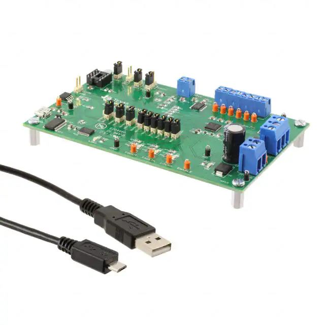
Figure 1 illustrates the top view of the DRV8307 EVM PCB.
Figure 1. DRV8307EVM Top View
2
Introduction
The DRV8307EVM is a solution for evaluating the DRV8307, a brushless DC motor controller. It includes
a TLC555 timer configuration to supply PWM to the DRV8307, a potentiometer to adjust the speed of the
motor by varying the duty cycle of the PWM, and an external PWM input pin. The EVM also supports
differential and single-ended hall sensors. The EVM includes surface-mounted test pins for all important
signals on the board. The DRV8307EVM is configured so that only connections to the motor, hall sensors
and power supply are required.
2.1
Power Connectors
The DRV8307EVM uses a single power supply rail which must be connected to terminal P1. Minimum
recommended VM of the EVM is 8.5 V and maximum is 32 V, with a current of at least 2A. A higher
current setting is recommended to maintain a stable VM voltage. Please refer to the DRV8307 datasheet
(SLVSCK2) for complete voltage range information. When power is supplied to the board, a green LED
(D4) in the lower left corner should light up.
2
DRV8307 User’s Guide
SLVUA58 – April 2014
Submit Documentation Feedback
Copyright © 2014, Texas Instruments Incorporated
�Introduction
www.ti.com
2.2
Test Points
Test points are provided and labeled according to the inputs and outputs of the DRV8307 device. The
signals brought out to test points are labeled HALLOUT, FAULTn, LOCKn, ENABLE, HU+/-, HV+/- HW+/and GND (Figure 2).
Figure 2. DRV8307EVM Test Points and FAULTn LED
The HALLOUT signal represents the motor speed and phase information.
RPM = (HALLOUT × 60) / pole pairs
(1)
The FAULTn and LOCKn signals represent DRV8307 outputs and indicate a fault or lock condition of the
driver or motor. If there is a fault condition present, a red LED (D3) lights up. LOCKn indicates whether the
speed loop is locked.
The HU+/-, HV+/- HW+/- represent the corresponding hall signals. The ENABLE pin represents whether
the DRV8307 is active or off.
The ENABLE signal is active low. The DRV8307 can be disabled by applying a high voltage to this pin.
SLVUA58 – April 2014
Submit Documentation Feedback
DRV8307 User’s Guide
Copyright © 2014, Texas Instruments Incorporated
3
�Introduction
2.3
www.ti.com
Jumpers
Seven jumpers (JP1–JP7) are installed by default on the EVM.
Table 1. Jumper Descriptions
Jumper
Description
JP1
HALL POWER: Hall sensor power is “5V” or “current”
JP2
JP3
HALL SIGNALS: Hall Signals are “Differential” or “Single Ended”
JP4
JP5
DIRECTION: Motor direction is “forward” or “reverse”
JP7
BRAKE: Motor brake “ON” or “OFF”
JP6
SPEED: Speed input is from supplied “external” or “potentiometer”
The default jumper settings are JP1 2-3, JP2, JP3 1-2, JP4 2-3 and JP5, JP6, JP7 all installed. This
supports "inverse" single-ended hall sensors supplied with 5 V. Speed is supplied from the potentiometer
and the motor spins in a forward direction and is not braked.
Figure 3. DRV8308EVM Jumpers
4
DRV8307 User’s Guide
SLVUA58 – April 2014
Submit Documentation Feedback
Copyright © 2014, Texas Instruments Incorporated
�Introduction
www.ti.com
2.3.1
HALL POWER Configuration (JP1/JP2 ) Jumpers
Sensored BLDC motors typically use either Hall ICs or Hall elements. Most ICs can use 5-V power, while
elements typically have power pins that have an equivalent circuit of a resistor, and current must be
limited to about 10 mA. In order to support both Hall sensor types the hall power needs to be configured
on the DRV8307EVM.
When installing JP1 2-3 and JP2, a 5-V power is supplied to terminal P3 to power the ICs. The used
(VREG) voltage is only present when DRV8307 is enabled and regulated from VM (Figure 4).
Figure 4. Hall PWR/GND Circuits
By installing JP1 1-2 and uninstalling JP2, the circuit illustrated in Figure 5 is available for the Hall
elements. The used (VSW) voltage is only present when DRV8307 is enabled. VSW equals VM.
Hall Elements
VM
180
HGND
HPWR
2 k
VSW
DRV8307
Figure 5. Circuit when Setting Hall Power to “Current”
The current can be calculated as follows: If VM is 24 V, and 3 Hall elements having a resistance of 400 Ω
are connected in parallel, 10.4 mA is supplied. Always refer to your Hall element specifications to
understand the proper current. The purpose of the 180-Ω resistor is to bias-up the common mode voltage
of Hall element differential signals, since the DRV8307 requires VICM between 1.5 V to 3.5 V.
If you are unsure of your motor’s Hall type, measure the resistance between the Hall power and ground
wires. If it is < 250 Ω, they are likely Hall elements. Hall sensors are easily damaged if incorrect power is
applied.
2.3.2
HALL SIGNAL Configuration (JP3/JP4) Jumpers
Hall sensors output either a differential signal pair, or a single-ended signal. You can tell which type your
motor uses simply by counting the number of wires; a sensored BLDC typically has 3 phase wires, 2 Hall
power wires, and 3 or 6 Hall signal wires, so 8 total means single-ended, and 11 total means differential.
The DRV8307 has differential comparators on the Hall inputs, and they can also accommodate singleended signals with the use of a few passive components. When using differential Halls, directly connect
the 6 Hall signals to the DRV8307 pins.
When using single-ended Halls, they require pull-ups. The DRV8307 comparator “-” pins should be biased
with a middle voltage, so that a single-ended swing on the “+” pin is detected like a differential voltage.
Connect single-ended hall wires to the "+" pins at P3 for normal Hall sensor types or to "-" pins for inverse
Hall sensors.
SLVUA58 – April 2014
Submit Documentation Feedback
DRV8307 User’s Guide
Copyright © 2014, Texas Instruments Incorporated
5
�Introduction
www.ti.com
In order to support both single ended and differential hall signals on the DRV8307EVM, the circuit in
Figure 6 is implemented:
5V
5V
1
2V
Terminal P3
Switch A
JP3
Switch A
2
DRV8307
Switch B
Block H+
IN
3
Switch D
HALL_U+
5V
Switch C
2V
5V
1
Switch A
Block HIN
Switch B
Switch B
JP4
Switch C
2
HALL_U3
Switch D
Figure 6. Switching Logic to Support Single-Ended and Differential-Hall Signals
Table 2 shows the configuration possibilities supporting a variety of hall sensors.
Table 2. Hall Sensors
2.3.3
Configuration
JP3
JP4
Comment
Terminal Installation
Differential Hall (Normal)
1-2
1-2
Switches A+B open
Hall wires in normal order
Differential Hall (Inverse)
1-2
1-2
Switches A+B open
Swap external Hall wires
Single Ended (Normal)
2-3
2-3
Switch A closed, B open
Hall wires to "+" pins
Single Ended (Inverse)
1-2
2-3
Switch A open, B close
Swap external Hall wires and connect to "-" pins
RESERVED
2-3
1-2
NOT ALLOWED
DIR Direction (JP5) Jumper
Installing the jumper JP5 connects the DIR pin on the DRV8307 to GND. When the DIR pin is tied to
GND, the DRV8307 connected motor is set to spin in the forward direction. When removed, the pin is
pulled high and the motor spins in the reverse direction.
2.3.4
BRAKE (JP7) Jumper
Installing the jumper JP7 connects the BRAKE pin on the DRV8307 to GND. When the BRAKE pin is tied
to GND, the DRV8307 connected motor is spinning normal without any brake action. When removed, the
pin is pulled high and the motor will be braked by the DRV8307 brake functionality.
6
DRV8307 User’s Guide
SLVUA58 – April 2014
Submit Documentation Feedback
Copyright © 2014, Texas Instruments Incorporated
�Introduction
www.ti.com
2.4
SPEED ADJUSTMENT (JP6) Jumper and (R20) Potentiometer
The DRV8307 has a dedicated speed input pin (PWM) that supplies a duty cycle to the DRV8307 to
control motor speed.
Figure 7. SPEED Adjustment Configuration
The DRV8307EVM offers two possibilities to supply this PWM input, controlled by jumper JP6.
Installing JP6 uses the speed adjust potentiometer SPEED ADJUST (R20) as shown in Figure 7 as PWM
speed input. The potentiometer adjusts the duty cycle of the PWM signal which, in turn, adjusts the speed
of the motor. The lower the duty cycle, therefore, the lower the speed, by turning the potentiometer
counter-clockwise. In order to increase the duty cycle, thus increase the speed, turn the potentiometer
clockwise.
The onboard PWM signal for the DRV8307 is generated by a circuit based upon TI's TLC555 Low-Power
Timer. It is capable of approximately a 25-kHz output that can be adjusted from 5% to 95% duty cycle.
This square output signal will switch from 0 V to VREG.
In order to provide an external PWM signal to the DRV8307, remove JP6 and connect the external PWM
signal to JP6 pin 1 and the GND pin next to it. For more information on the PWM input required by the
DRV8307, please refer to the DRV8307 datasheet (SLVSCK2).
SLVUA58 – April 2014
Submit Documentation Feedback
DRV8307 User’s Guide
Copyright © 2014, Texas Instruments Incorporated
7
�Introduction
2.5
www.ti.com
Operation of the EVM
The following steps provide instructions for the operation of the EVM:
1. Connect a three-phase BLDC motor to terminal P2.
2. Connect the hall signals, either single ended or differential, to terminal P3.
3. Configure JP1-JP4 in order to supply the hall signals in the right manner to the DRV8307.
4. Adjust the Speed potentiometer, R20, to minimum voltage by turning it all the way counterclockwise.
This minimizes the motor speed. Otherwise, connect your external PWM input to the JP6 PWM pin.
5. Check JP5 and JP7 to be installed.
6. Apply power to VM terminal P1.
7. Adjust the potentiometer clockwise or turn your external PWM source ON to increase the speed of the
motor, continue adjusting as desired.
8. To change direction, uninstall JP5.
9. To start braking, uninstall JP7.
8
DRV8307 User’s Guide
SLVUA58 – April 2014
Submit Documentation Feedback
Copyright © 2014, Texas Instruments Incorporated
�Schematic and Bill of Materials
www.ti.com
3
Schematic and Bill of Materials
Figure 8 illustrates the DRV8307EVM schematic and Table 3 is the DRV8307EVM BOM.
Jumper List
VM
P1
2
1
D4
Green
Test Points
Single Ended HALL
normal / inverse
TP1
TP2
JP5
Direction
Installed is Low
JP7
Brake
Installed is Low
TP3
TP4
TP5
TP6
Speed Adjust
JP8
1
HU-
1
HU+
1
HV-
1
HV+
1
HW-
1
TP7
TP8
TP9
TP10
TP11
U14
1
ENABLE#
1
HALLOUT
1
VM
1
LOCKn
1
FAULTn
TP13
1
1
2
JP3
JP4
2
D6
1.5SMC33
C1
220uF
Power
input
OSTTA024163
C2
0.1uF
GND
1
KA
1
Hall power: 5V or
current
2
JP1
JP2
R15
4.3K
GND
U13
1
2
OPTIONAL: Serial Resistors slow
FET turn-on time and reduce noise
HW+
Installed: R20 Poti controls speed
Uninstalled: Ext. PWM input to JP6
GND
Default to populate:
UHS_GATE
R24
240
ULS_GATE
R25
0
D1
U2
1
2
3
4
S1
G1
S2
G2
JP1_2-3, JP2
JP3_1-2, JP4_2-3
JP5, JP7, JP8
D1
D1
D2
D2
G1
8
7
6
5
S1
U
D2
G2
CSD88537ND
S2
U3
These circuits control whether pullup resistors and 2V biases are connected
to the DRV8307 Hall inputs. Configuration is done by 2 jumpers (JP3, JP4),
and it's provided to support differential Hall signals and single-ended Hall
signals with any High/Low polarity. The purpose of the 2V bias is to
connect to one end of each DRV8307 differential comparator, so that the
single-ended signal swings 0V to 4V and is detected like a differential voltage.
In general, if the resistance between the Hall PWR and
GND wires is


 工商网监
湘ICP备2023018690号
工商网监
湘ICP备2023018690号
