User's Guide
SNVA506A – October 2011 – Revised May 2013
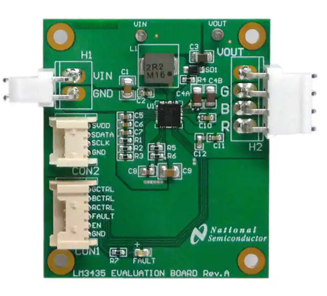
AN-2196 LM3435 Evaluation Board
1
Introduction
The Texas Instruments LM3435 Evaluation Board has been designed for evaluating the performance of
the device in a typical pico projector application. The end user can interface his own system to the
evaluation board to test out the performance of the system. With LM3435, the system requires only single
DC-DC converter to drive three color LEDs instead of using three DC-DC converters with conventional
design. The suggested approach not only saves components cost, but also releases invaluable PCB
space to the system and enhances system reliability. Assuming the handy projector is powered by a single
lithium battery cell or a 5Vdc wall mount adaptor, the key specifications of the evaluation board are:
Supply voltage range, VIN = 2.7V to 5.5V
Preset LED current per channel, ILED = 1.5A
Minimum LED current per channel, ILED(MIN) = 600mA
Maximum LED forward voltage drop, VLED = 3.5V @ 1.5A
Flyback converter switching frequency, FSW = ~500kHz
2
Evaluation Board Schematic Diagram
The complete schematic diagram of the evaluation board is shown in Figure 1. For the details of the
design, please see LM3435 Compact Sequential Mode RGB LED Driver with I2C Control Interface
(SNVS724).
3
Connecting the Evaluation Board to the System
The LM3435 Evaluation Board is optimized to run with input voltages ranging from 2.7V to 5.5V and
requires a supply current not less than 4.1A for full range operation. A connection diagram to show the
configuration between the system and the evaluation board is shown in Figure 2. Proper connections to
the I/Os must be confirmed before powering up the board. In order to avoid false triggering of the
OPEN/SHORT fault detect of the device, the control pins GCTRL, BCTRL, and RCTRL must be kept in
logic “LOW” during power-up.
4
Interfacing with the I2C Bus
The current setting resistors only determine the nominal maximum LED current and the actual LED
current can be further adjusted on-the-fly by the internal ten bits register for individual channel. The
content of these registers are user programmable via standard I2C bus. The connection between the
system MCU and the I2C bus is illustrated in Figure 2. The resolution is 1 out of 1024 part of the LED
current setting. The user can program the registers in the range from full output, that is, 1023 (3FFH) to
minimum LED current that is restricted by the inductor ripple current amplitude. For Projected On-Time
(POT) scheme used in LM3435, a minimum inductor ripple current of 300mAPK-PK is required to maintain
proper operation. For the details of the registers addresses and definitions, please see LM3435 Compact
Sequential Mode RGB LED Driver with I2C Control Interface (SNVS724).
All trademarks are the property of their respective owners.
SNVA506A – October 2011 – Revised May 2013
Submit Documentation Feedback
Copyright © 2011–2013, Texas Instruments Incorporated
AN-2196 LM3435 Evaluation Board
1
�Interfacing with the GPIO Bus
5
www.ti.com
Interfacing with the GPIO Bus
The PWM control pins GCTRL, BCTRL, and RCTRL are internally pulled low, push-pull I/O ports are
recommended to interface properly with the system MCU. The device enable, EN pin is internally pulled
high, so an open drain I/O port is recommended.
6
Changing the Preset LED Current
The factory preset LED current of the LM3435 evaluation board is 1.5A, In case the user need to make a
change of the preset LED current, it can be done by simply replacing the LED current setting resistors R1,
R2 and R3. The ILED(MIN) condition should not be violated for proper regulation, that is, the ILED current for all
operation conditions must be no less than 600mA with this evaluation board. Some popular values for
user's reference are listed in below. For details about the operation and calculations of the components,
please see LM3435 Compact Sequential Mode RGB LED Driver with I2C Control Interface (SNVS724).
Preset LED Current, ILED
2
R1, R2, R3 Value
1.5A
16.5kΩ
1.0A
24.75kΩ
0.75A
33.0kΩ
AN-2196 LM3435 Evaluation Board
SNVA506A – October 2011 – Revised May 2013
Submit Documentation Feedback
Copyright © 2011–2013, Texas Instruments Incorporated
�Evaluation Board Schematic
www.ti.com
7
Evaluation Board Schematic
C3
VIN
VOUT
10 PF
L1
2.2 PH/6A
C1
Power
Input
47 PF
C2
0.1 PF
SD1
RB160M-60
GND
H1
C4A
31
32
VOUT
33
34
RT
35
SW
36
SW
37
SW
38
VIN
39
PGND
3
CG
EN
C6
4
CB
C7
5
CR
R1
6
IREFG
R2
7
IREFB
BLED
R3
8
IREFR
BLED
9
GND
RLED
GLED
RCTRL
RLED
30
29
28
VOUT
27
26
GRN
C10
25
24
To LEDs
BLU
23
C11
22
21
C12
RED
H2
3 x 0.47PF
20
BCTRL
19
GCTRL
GLED
18
VIN
VIN
VIN
SCLK
VIN
17
16
C9
47 PF
15
C8
1 PF
SGND
14
10
13
16.5k
FAULT
DAP
(PGND)
SDATA
16.5k
16.5k
VOUT
SGND
SVDD
1 nF
PGND
12
1 nF
2 x 10 PF
2
11
1 nF
C5
VOUT
1
PGND
PGND
U1
PGND
40
R4
499k
C4B
SVDD
*R5
10k
2
I C Bus
*R6
10k
R7 1k
SDATA
SCLK
GND
* R5, R6 - I2C Pull-high resistors
FAULT
CON2
GCTRL
PWM Controls
And
GPIO Bus
BCTRL
RCTRL
FAULT
EN
GND
CON1
Figure 1. Evaluation Board Schematic Diagram
SNVA506A – October 2011 – Revised May 2013
Submit Documentation Feedback
Copyright © 2011–2013, Texas Instruments Incorporated
AN-2196 LM3435 Evaluation Board
3
�Connection Diagrams
8
www.ti.com
Connection Diagrams
VOUT - VIN
V
2.7V ± 5.5V
5A
Power Supply
+
+
VIN
** Use current probe to
monitor the LED current
+
V
-
ILED
IIN
+
A
GRN LED
RED
LED
GND
SCLK
SDA
SVDD
BLU
LED
2
I C Bus
&XVWRPHU¶V
MCU Board
GCTRL
BCTRL
RCTRL
FAULT
EN
GND
GPIO Bus
Fault Indicator
Figure 2. Evaluation Setup Connection Diagram
4
AN-2196 LM3435 Evaluation Board
SNVA506A – October 2011 – Revised May 2013
Submit Documentation Feedback
Copyright © 2011–2013, Texas Instruments Incorporated
�Typical Performance Waveforms
www.ti.com
9
Typical Performance Waveforms
All curves taken at VIN = 5V with configuration in typical application for driving one red (OSRAM
LRW5AP-KZMX), one green (OSRAM LTW5AP-LZMY) and one blue (OSRAM LBW5AP-JYKX) LEDs with
ILED per channel = 1.5A under TA = 25°C, unless otherwise specified.
2.5
90
2.0
BLUE
ILEDx(A)
LED EFFICIENCY, (%)
100
80
GREEN
70
1.5
1.0
RED
60
0.5
50
0.0
2
3
4
VIN(V)
5
6
5
15
25
35
RIREFx(k )
45
55
Figure 3. LED Efficiency vs VIN@ TA=25°C
Figure 4. ILEDx vs RIREFx
Figure 5. Power Up Transient (10ms/DIV)
Figure 6. RGB Sequential Mode Operation (1ms/DIV)
SNVA506A – October 2011 – Revised May 2013
Submit Documentation Feedback
Copyright © 2011–2013, Texas Instruments Incorporated
AN-2196 LM3435 Evaluation Board
5
�Typical Performance Waveforms
www.ti.com
Figure 7. Color Transition Delay (100µs/DIV)
6
AN-2196 LM3435 Evaluation Board
SNVA506A – October 2011 – Revised May 2013
Submit Documentation Feedback
Copyright © 2011–2013, Texas Instruments Incorporated
�Bill of Materials
www.ti.com
10
Bill of Materials
In order to help customer shorten the design cycle of the target application system, a detailed list of all
components used in this evaluation board is provided.
ID
Part Number
Type
Size
Parameters
Qty
Su
U1
LM3435
RGB LED Driver
IC
WQFN-40
1
Texas
Instruments
SD1
RB160M-60
Schottky Diode
SOD-123
1A, 60V, Vf = 0.49V
1
Rohm
L1
CDMC6D28NP-2R2MC
Power Inductor
7mm x 7mm
2.2µH, 6A, 19mΩ
1
Sumida
C1, C9
GRM31CR61A476M
Ceramic
Capacitor
1206
47µF, 10V, X5R
2
Murata
C2
GRM188R61E104K
Ceramic
Capacitor
0603
0.1µH 25V, X5R
1
Murata
C3, C4A,
C4B
GJ831CR61E106K
Ceramic
Capacitor
1206
10µF, 25V, X5R
3
Murata
C5, C6, C7
GRM188R71H102K
Ceramic
Capacitor
0603
1nF, 50V, X7R
3
Murata
C8
GRM188R71A105K
Ceramic
Capacitor
0603
1µF, 10V, X7R
1
Murata
C10, C11.
C12
GRM188R71E474K
Ceramic
Capacitor
0603
0.47µF, 25V, X7R
3
Murata
R1, R2, R3
SMT Resistor
0603
16.5kΩ, ±1%
3
R4
SMT Resistor
0603
499kΩ, ±1%
1
R5, R6
SMT Resistor
0603
10kΩ, ±1%
2
R7
SMT Resistor
0603
1kΩ, ±1%
1
FAULT
LTST-C170EKT
SMT LED
0805
LED RED ORANGE
1
Lite-On
VIN, VOUT
1593–2
Terminal Pin
Φ2.35mm
Turret DBL, 2.34mm
1
Keystone
H1
B2PS-VH
Connector
Header
2 Position, Pitch
3.96mm
1
JST
H2
B4PS-VH
Connector
Header
4 Position, Pitch
3.96mm
1
JST
CON1
35363–0660
Connector
Header
6 Position, Pitch 2mm
1
Molex
CON2
35363–0460
Connector
Header
4 Position, Pitch 2mm
1
Molex
SNVA506A – October 2011 – Revised May 2013
Submit Documentation Feedback
Copyright © 2011–2013, Texas Instruments Incorporated
AN-2196 LM3435 Evaluation Board
7
�PCB Layout
PCB Layout
58 mm
11
www.ti.com
50 mm
Figure 8. Top Overlay
8
AN-2196 LM3435 Evaluation Board
SNVA506A – October 2011 – Revised May 2013
Submit Documentation Feedback
Copyright © 2011–2013, Texas Instruments Incorporated
�PCB Layout
58 mm
www.ti.com
50 mm
58 mm
Figure 9. Top Layer
50 mm
Figure 10. Bottom Layer
SNVA506A – October 2011 – Revised May 2013
Submit Documentation Feedback
Copyright © 2011–2013, Texas Instruments Incorporated
AN-2196 LM3435 Evaluation Board
9
�IMPORTANT NOTICE
Texas Instruments Incorporated and its subsidiaries (TI) reserve the right to make corrections, enhancements, improvements and other
changes to its semiconductor products and services per JESD46, latest issue, and to discontinue any product or service per JESD48, latest
issue. Buyers should obtain the latest relevant information before placing orders and should verify that such information is current and
complete. All semiconductor products (also referred to herein as “components”) are sold subject to TI’s terms and conditions of sale
supplied at the time of order acknowledgment.
TI warrants performance of its components to the specifications applicable at the time of sale, in accordance with the warranty in TI’s terms
and conditions of sale of semiconductor products. Testing and other quality control techniques are used to the extent TI deems necessary
to support this warranty. Except where mandated by applicable law, testing of all parameters of each component is not necessarily
performed.
TI assumes no liability for applications assistance or the design of Buyers’ products. Buyers are responsible for their products and
applications using TI components. To minimize the risks associated with Buyers’ products and applications, Buyers should provide
adequate design and operating safeguards.
TI does not warrant or represent that any license, either express or implied, is granted under any patent right, copyright, mask work right, or
other intellectual property right relating to any combination, machine, or process in which TI components or services are used. Information
published by TI regarding third-party products or services does not constitute a license to use such products or services or a warranty or
endorsement thereof. Use of such information may require a license from a third party under the patents or other intellectual property of the
third party, or a license from TI under the patents or other intellectual property of TI.
Reproduction of significant portions of TI information in TI data books or data sheets is permissible only if reproduction is without alteration
and is accompanied by all associated warranties, conditions, limitations, and notices. TI is not responsible or liable for such altered
documentation. Information of third parties may be subject to additional restrictions.
Resale of TI components or services with statements different from or beyond the parameters stated by TI for that component or service
voids all express and any implied warranties for the associated TI component or service and is an unfair and deceptive business practice.
TI is not responsible or liable for any such statements.
Buyer acknowledges and agrees that it is solely responsible for compliance with all legal, regulatory and safety-related requirements
concerning its products, and any use of TI components in its applications, notwithstanding any applications-related information or support
that may be provided by TI. Buyer represents and agrees that it has all the necessary expertise to create and implement safeguards which
anticipate dangerous consequences of failures, monitor failures and their consequences, lessen the likelihood of failures that might cause
harm and take appropriate remedial actions. Buyer will fully indemnify TI and its representatives against any damages arising out of the use
of any TI components in safety-critical applications.
In some cases, TI components may be promoted specifically to facilitate safety-related applications. With such components, TI’s goal is to
help enable customers to design and create their own end-product solutions that meet applicable functional safety standards and
requirements. Nonetheless, such components are subject to these terms.
No TI components are authorized for use in FDA Class III (or similar life-critical medical equipment) unless authorized officers of the parties
have executed a special agreement specifically governing such use.
Only those TI components which TI has specifically designated as military grade or “enhanced plastic” are designed and intended for use in
military/aerospace applications or environments. Buyer acknowledges and agrees that any military or aerospace use of TI components
which have not been so designated is solely at the Buyer's risk, and that Buyer is solely responsible for compliance with all legal and
regulatory requirements in connection with such use.
TI has specifically designated certain components as meeting ISO/TS16949 requirements, mainly for automotive use. In any case of use of
non-designated products, TI will not be responsible for any failure to meet ISO/TS16949.
Products
Applications
Audio
www.ti.com/audio
Automotive and Transportation
www.ti.com/automotive
Amplifiers
amplifier.ti.com
Communications and Telecom
www.ti.com/communications
Data Converters
dataconverter.ti.com
Computers and Peripherals
www.ti.com/computers
DLP® Products
www.dlp.com
Consumer Electronics
www.ti.com/consumer-apps
DSP
dsp.ti.com
Energy and Lighting
www.ti.com/energy
Clocks and Timers
www.ti.com/clocks
Industrial
www.ti.com/industrial
Interface
interface.ti.com
Medical
www.ti.com/medical
Logic
logic.ti.com
Security
www.ti.com/security
Power Mgmt
power.ti.com
Space, Avionics and Defense
www.ti.com/space-avionics-defense
Microcontrollers
microcontroller.ti.com
Video and Imaging
www.ti.com/video
RFID
www.ti-rfid.com
OMAP Applications Processors
www.ti.com/omap
TI E2E Community
e2e.ti.com
Wireless Connectivity
www.ti.com/wirelessconnectivity
Mailing Address: Texas Instruments, Post Office Box 655303, Dallas, Texas 75265
Copyright © 2013, Texas Instruments Incorporated
�


 工商网监
湘ICP备2023018690号
工商网监
湘ICP备2023018690号
