6N137, CT2601
10MBit/s High Speed Logic Gate Optocoupler
Features
Description
High speed 10MBit/s
The 6N137, CT2601 optocouplers consist of a 850
High isolation voltage between input and output
nm AlGaAS LED, optically coupled to a very high
speed integrated photo-detector logic gate with a
(Viso=5000 Vrms )
Guaranteed
Wide operating temperature range of -55°C to
strobable output. This output features an open
performance from -40°C to 85°C
collector,
there by permitting wired OR outputs. The switching
100°C
parameters are guaranteed over the temperature
Regulatory Approvals
range of -40°C to +85°C. A maximum input signal of
UL - UL1577 (E364000)
VDE - EN60747-5-5(VDE0884-5)
CQC – GB4943.1, GB8898
13mA (fan out of 8).
IEC60065, IEC60950
Applications
5mA will provide a minimum output sink current of
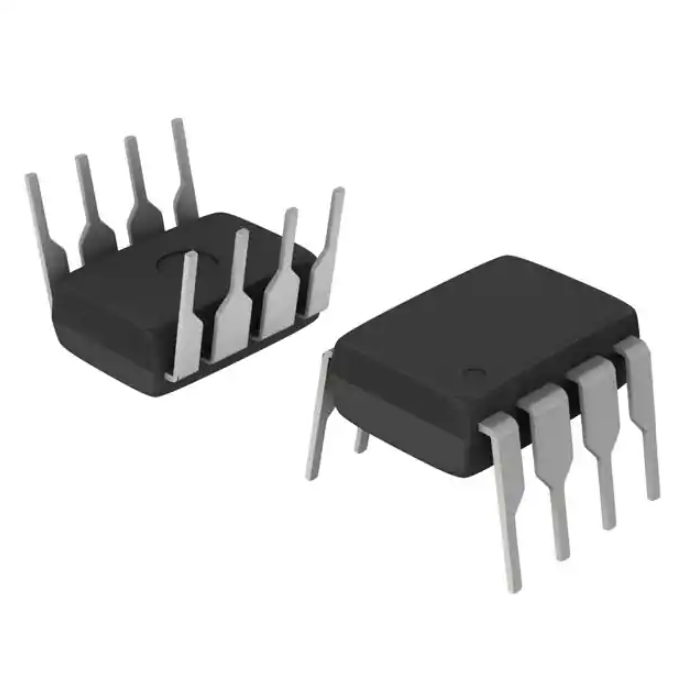
Package Outline
Line receivers
Telecommunication equipment
Feedback loop in switch-mode power supplies
Home appliances
High speed logic ground isolation
Schematic
Note: Different lead forming options available. See package
dimension.
CT Micro
Proprietary & Confidential
Page 1
Rev 4
Jan, 2018
�6N137, CT2601
10MBit/s High Speed Logic Gate Optocoupler
Absolute Maximum Rating at 25oC
Symbol
Parameters
Ratings
Units
Notes
5000
VRMS
1
VISO
Isolation voltage
TOPR
Operating temperature
-55 ~ +100
oC
TSTG
Storage temperature
-55 ~ +125
oC
TSOL
Soldering temperature
260
oC
IF
Forward current
50
mA
VR
Reverse voltage
5
V
PI
Power dissipation
100
mW
PO
Power dissipation
85
mW
IO
Average Output current
50
mA
VO
Output voltage
7.0
V
VCC
Supply voltage
7.0
V
VE
Enable Input Voltage Not to Exceed VCC by more than 500mV
5.5
V
2
Emitter
Detector
1min(Max.)
Notes
1. AC for 1 minute, RH = 40 ~ 60%.
2. For 10 second peak
CT Micro
Proprietary & Confidential
Page 2
Rev 4
Jan, 2018
�6N137, CT2601
10MBit/s High Speed Logic Gate Optocoupler
Electrical Characteristics
TA = -40 - 85°C (unless otherwise specified). Typical values are measured at TA = 250C and VCC=5V
Emitter Characteristics
Symbol
Parameters
Test Conditions
Min
Typ
Max
Units
VF
Forward voltage
IF = 10mA
-
1.4
1.6
V
VR
Reverse Voltage
IR = 10μA
5.0
-
-
V
IF =10mA
-
-1.8
-
mV/°C
Test Conditions
Min
Typ
Max
Units
IF=0mA, VE=0.5V, VCC=3.3V
-
4.0
10
IF=0mA, VE=0.5V, VCC=5.5V
-
6.5
10
IF=10mA, VE=0.5V, VCC=3.3V
-
5.5
13
IF=10mA, VE=0.5V, VCC=5.5V
-
8.8
13
IF=10mA, VCC=3.3V
2.0
-
-
IF=10mA, VCC=5.5V
2.0
-
-
IF=10mA, VCC=3.3V
-
-
0.8
IF=10mA, VCC=5.5V
-
-
0.8
VE=2.0V, VCC=3.3V
-
-0.2
-1.6
VE=2.0V, VCC=5.5V
-
-0.53
-1.6
VE=0.5V, VCC=3.3V
-
-0.42
-1.6
VE=0.5V, VCC=5.5V
-
-0.75
-1.6
Min
Typ
Max
-
1.6
5
ΔVF/ΔTA
Notes
Temperature coefficient of forward
voltage
Detector Characteristics
Symbol
ICCH
ICCL
VEH
VEL
IEH
IEL
Parameters
Logic High Supply Current
Notes
mA
Logic Low Supply Current
mA
High Level Enable Voltage
V
Low Level Enable Voltage
V
High Level Enable Current
mA
Low Level Enable Current
mA
Transfer Characteristics
Symbol
Parameters
Test Conditions
Units
Notes
VCC=3.3V, VO=0.6V,
VE=2.0V, IO=13mA
IFT
Input Threshold Current
mA
VCC=5.5V, VO=0.6V,
-
2.5
5
VE=2.0V, IO=13mA
CT Micro
Proprietary & Confidential
Page 3
Rev 4
Jan, 2018
�6N137, CT2601
10MBit/s High Speed Logic Gate Optocoupler
IF=250µA, VO=VCC=3.3V,
-
7.0
100
VE =2.0V
IOH
Logic High Output Current
µA
IF=250µA, VO=VCC=5.5V,
-
2.0
100
-
0.45
0.6
VE =2.0V
IF=5mA, VCC=3.3V, VE=2.0V,
IO=13mA
VOL
Low Level Output Voltage
V
IF=5mA, VCC=5.5V, VE=2.0V,
-
0.35
0.6
IO=13mA
Electrical Characteristics
TA = -40 - 85°C (unless otherwise specified). Typical values are measured at TA = 250C, VCC=5V and IF= 7.5mA
Switching Characteristics
Symbol
Parameters
Test Conditions
Min
Typ
Max
Output Propagation Delay High to
CL= 15pF, RL= 350Ω VCC=3.3V
-
34
75
Low
CL= 15pF, RL= 350Ω VCC=5.5V
-
34
75
Output Propagation Delay Low to
CL= 15pF, RL= 350Ω VCC=3.3V
-
50
75
TPHL
ns
High
Tr
Tf
Notes
ns
TPLH
PWD
Units
CL= 15pF, RL= 350Ω VCC=5.5V
-
39
75
CL= 15pF, RL= 350Ω VCC=3.3V
-
16
34
CL= 15pF, RL= 350Ω VCC=5.5V
-
5
34
CL= 15pF, RL= 350Ω VCC=3.3V
-
37
-
CL= 15pF, RL= 350Ω VCC=5.5V
-
37
-
CL= 15pF, RL= 350Ω VCC=3.3V
-
10
-
CL= 15pF, RL= 350Ω VCC=5.5V
-
10
-
-
15
-
ns
-
15
-
ns
-
10000
-
Pulse Width Distortion
Output Rise Time
Output Fall Time
ns
ns
ns
Enable Propagation Delay Low To
TELH
High
VEH= 3.5V, CL= 15pF, RL=
Enable Propagation Delay High
350Ω
TEHL
To Low
IF= 0mA,
6N137
Common Mode Transient
VCM= 50Vp-p,
Immunity at Logic High
VOH= 2.0V,
CMH
V/µs
CT2601
5000
10000
-
RL= 350Ω
CT Micro
Proprietary & Confidential
Page 4
Rev 4
Jan, 2018
�6N137, CT2601
10MBit/s High Speed Logic Gate Optocoupler
IF=7.5mA,
6N137
Common Mode Transient
VCM= 50Vp-p,
Immunity at Logic Low
VOL= 0.8V,
-
10000
-
CML
V/µs
CT2601
5000
10000
-
RL= 350Ω
CT Micro
Proprietary & Confidential
Page 5
Rev 4
Jan, 2018
�6N137, CT2601
10MBit/s High Speed Logic Gate Optocoupler
Typical Characteristic Curves
CT Micro
Proprietary & Confidential
Page 6
Rev 4
Jan, 2018
�6N137, CT2601
10MBit/s High Speed Logic Gate Optocoupler
Typical Characteristic Curves
CT Micro
Proprietary & Confidential
Page 7
Rev 4
Jan, 2018
�6N137, CT2601
10MBit/s High Speed Logic Gate Optocoupler
CT Micro
Proprietary & Confidential
Page 8
Rev 4
Jan, 2018
�6N137, CT2601
10MBit/s High Speed Logic Gate Optocoupler
CT Micro
Proprietary & Confidential
Page 9
Rev 4
Jan, 2018
�6N137, CT2601
10MBit/s High Speed Logic Gate Optocoupler
Test Circuits
Switching Time Test Circuit
CT Micro
Proprietary & Confidential
Page 10
Rev 4
Jan, 2018
�6N137, CT2601
10MBit/s High Speed Logic Gate Optocoupler
Test Circuits
Enable Switching Time Test Circuit
CT Micro
Proprietary & Confidential
Page 11
Rev 4
Jan, 2018
�6N137, CT2601
10MBit/s High Speed Logic Gate Optocoupler
Test Circuits
CMR Test Circuit
CT Micro
Proprietary & Confidential
Page 12
Rev 4
Jan, 2018
�6N137, CT2601
10MBit/s High Speed Logic Gate Optocoupler
Package Dimension Dimensions in mm unless otherwise stated
Standard DIP – Through Hole
Gullwing (400mil) Lead Forming – Through Hole (M Type)
CT Micro
Proprietary & Confidential
Page 13
Rev 4
Jan, 2018
�6N137, CT2601
10MBit/s High Speed Logic Gate Optocoupler
Surface Mount Lead Forming (S Type)
Surface Mount (Low Profile) Lead Forming (SL Type)
CT Micro
Proprietary & Confidential
Page 14
Rev 4
Jan, 2018
�6N137, CT2601
10MBit/s High Speed Logic Gate Optocoupler
Wide Surface Mount Forming (Low Profile) – SLM Type)
Recommended Solder Mask Dimensions in mm unless otherwise stated
CT Micro
Proprietary & Confidential
Page 15
Rev 4
Jan, 2018
�6N137, CT2601
10MBit/s High Speed Logic Gate Optocoupler
Device Marking
CT
CT
6N137
2601
VYWWK
VYWWK
Note:
CT
6N137
2601
V
: Denotes “CT Micro”
: Product Number
: Product Number
: VDE Option
Y
WW
K
: Fiscal Year
: Work Week
: Production Code
Ordering Information
6N137(V)(Y)(Z)-G ; CT2601(V)(Y)(Z)-G
CT
6N137
2601
= Denotes “CT Micro”
= Part Number
= Part Number
V
Y
Z
G
= VDE Option ( V or None)
= Lead form option (S, SL, M , SLM or none)
= Tape and reel option (T1, T2 or none)
= Material option (G: Green, None: Non-green)
CT Micro
Proprietary & Confidential
Page 16
Rev 4
Jan, 2018
�6N137, CT2601
10MBit/s High Speed Logic Gate Optocoupler
Option
Description
Quantity
None
Standard 8 Pin Dip
40 Units/Tube
M
Gullwing (400mil) Lead Forming
40 Units/Tube
S(T1)
Surface Mount Lead Forming – With Option 1 Taping
1000 Units/Reel
S(T2)
Surface Mount Lead Forming – With Option 2 Taping
1000 Units/Reel
SL(T1)
Surface Mount (Low Profile) Lead Forming– With Option 1 Taping
1000 Units/Reel
SL(T2)
Surface Mount (Low Profile) Lead Forming– With Option 2 Taping
1000 Units/Reel
SLM(T1)
Surface Mount (Gullwing) Lead Forming– With Option 1 Taping
1000 Units/Reel
SLM(T2)
Surface Mount (Gullwing) Lead Forming – With Option 2 Taping
1000 Units/Reel
CT Micro
Proprietary & Confidential
Page 17
Rev 4
Jan, 2018
�6N137, CT2601
10MBit/s High Speed Logic Gate Optocoupler
Carrier Tape Specifications Dimensions in mm unless otherwise stated
Option S(T1) & SL(T1)
Option S(T2) & SL(T2)
CT Micro
Proprietary & Confidential
Page 18
Rev 4
Jan, 2018
�6N137, CT2601
10MBit/s High Speed Logic Gate Optocoupler
Option SLM(T1)
Option SLM(T2)
CT Micro
Proprietary & Confidential
Page 19
Rev 4
Jan, 2018
�6N137, CT2601
10MBit/s High Speed Logic Gate Optocoupler
Wave soldering (follow the JEDEC standard JESD22-A111)
One time soldering is recommended within the condition of temperature.
Temperature: 260+0/-5˚C.
Time: 10 sec.
Preheat temperature:25 to 140˚C.
Preheat time: 30 to 80 sec.
Iron soldering (follow the standard MIL-STD 202G, Method 210F)
Allow single lead soldering in every single process.
One time soldering is recommended. Temperature: 350+±10˚C
Time: 5 sec max.
CT Micro
Proprietary & Confidential
Page 20
Rev 4
Jan, 2018
�6N137, CT2601
10MBit/s High Speed Logic Gate Optocoupler
Reflow Profile
Profile Feature
Pb-Free Assembly Profile
Temperature Min. (Tsmin)
150°C
Temperature Max. (Tsmax)
200°C
Time (ts) from (Tsmin to Tsmax)
60-120 seconds
Ramp-up Rate (tL to tP)
3°C/second max.
Liquidous Temperature (TL)
217°C
Time (tL) Maintained Above (TL)
60 – 150 seconds
Peak Body Package Temperature
260°C +0°C / -5°C
Time (tP) within 5°C of 260°C
30 seconds
Ramp-down Rate (TP to TL)
6°C/second max
Time 25°C to Peak Temperature
8 minutes max.
CT Micro
Proprietary & Confidential
Page 21
Rev 4
Jan, 2018
�6N137, CT2601
10MBit/s High Speed Logic Gate Optocoupler
DISCLAIMER
CT MICRO RESERVES THE RIGHT TO MAKE CHANGES WITHOUT FURTHER NOTICE TO ANY PRODUCTS
HEREIN TO IMPROVE RELIABILITY, FUNCTION OR DESIGN. CT MICRO DOES NOT ASSUME ANY LIABILITY
ARISING OUT OF THE APPLICATION OR USE OF ANY PRODUCT OR CIRCUIT DESCRIBED HEREIN;
NEITHER DOES IT CONVEY ANY LICENSE UNDER ITS PATENT RIGHTS, NOR THE RIGHTS OF OTHERS.
______________________________________________________________________________________
CT MICRO ARE NOT AUTHORIZED FOR USE AS CRITICAL COMPONENTS IN LIFE SUPPORT DEVICES OR
SYSTEMS WITHOUT EXPRESS WRITTEN APPROVAL OF CT MICRO INTERNATIONAL CORPORATION.
1. Life support devices or systems are devices or
2. A critical component is any component of a life
systems which, (a) are intended for surgical
support device or system whose failure to perform
implant into the body, or (b) support or sustain life,
can be reasonably expected to cause the failure of
or (c) whose failure to perform when properly used
the life support device or system, or to affect its
in accordance with instruction for use provided in
safety or effectiveness.
the labelling, can be reasonably expected to result
in significant injury to the user.
CT Micro
Proprietary & Confidential
Page 22
Rev 4
Jan, 2018
�


 工商网监
湘ICP备2023018690号
工商网监
湘ICP备2023018690号

