www.breedelectronics.com
HE200 Features and Benefits
F eatures
Benefits
Applications
• Multi-pole configuration
(up to 5 normally open
contacts)
• Combination normally
open/normally closed
option
• Available with 5V, 12V or
24V coil options as
standard
• Magnetic shield option
• Lengthways coil option
• Staggered pins
• One relay, many contacts
reducing space and cost
without compromising
flexibility.
• Lower power coil
consumption than
competing
electromechanical
devices.
• Hermetically sealed
switching contact is
immune to the effects of
its environment.
• Security
• Telecoms
• Instrumentation
• Process Control
• Industrial
DIMENSIONS
Figure 1
Figure 2
HE200
HE200
Table 1
Relay Type
Case Size, Max.
HE200
Metal Case, (in.),mm
Plastic Case, (in.),mm
HE200 PCB
LA YOUT
(Bottom View)
All
h
All
l
1
w
2
w
3
w
(.375) 9,5
(.394) 10
(1.260) 32
(1.280) 32,5
(.394) 10
(.414) 10,5
(.493) 12,5
(.512) 13
(.591) 15
(.611) 15,5
ORDERING INFORMATION
PART NUMBER
HE2X
X
X
XX
X
X
Model Number
HE22 - Standard
HE25 - High Voltage
Coil Termination
0 - End Coil
1 - Lengthwise
Number of Contacts
1,2,3,4,5 (form A only)
Case Option
5 - Plastic case
9 - Metal case
Contact Type
A - Form A (SPST-NO)
B - Form B (SPST-NC)
C - Form C (SPDT-CO)
X - Combination Form A and B
Standard Coil
05 - 5 Volt
12 - 12 Volt
24 - 24 Volt
See next pa g e for : Electrical and Operating Characterisics Description and Coil Characteristics
PA GE 1 OF 2
�Table 2
HE200 Series
Column Number from
Contact Type
Electrical and Operating Characteristics
Table 3
Column 2
F orm C
Standar d
HE200
Column 3
Form A
High
Volta ge
HE200
Watt - max.
Vdc - max.
A - max.
A - max.
Vdc - min.
Vac - min.
10
200
0.5
1.2
250
1500
5
175
0.25
1.5
200
1500
10
300
0.5
1.5
450
1500
Vac - min.
Vac - min.
1500
1000
1500
1000
1500
1000
Ω - max.
Ω - min.
Ω - min.
0.150
1010
1010
0.150
109
1010
0.150
1010
1010
ms - max.
ms - max.
°C
°C
G - max.
10-2000 Hz.
G - max.
11 ms, 1⁄2 sine
1.0
1.0
-40 to +85
-40 to +105
20
3.0
3.0
-40 to +85
-40 to +105
20
1.0
1.0
-20 to +85
-40 to +105
20
50
50
50
Rela y Types
CONTACT RATINGS Power, Switching
Contact Hamlin
Voltage, Switching
for specific
Current,Switching
load/life details.
Current,Carry
VOLTAGE
Across Open Contacts
HOLD-OFF
Contacts to Coil
Between Isolated Terminals
Plastic case
Metal Case
RESISTANCE
Contact,Initial
Insulation:Across Open Contacts
Between Isolated Terminals
TIMING
Operate Time
Release Time
Temperature, Operating
Temperature, Storage
Vibration Resistance
ENVIRONMENTAL
Shock Resistance
Table 3
Contact Form
& Type
1A
SPST-NO
HE200 Series Miniature Rela
Electrical &
Operating
Characteristics
See Table 2
Column 1
Dimensions
Case Siz e
P art Number
Note 1
Table 1
Column 1
HE221A0550
HE221A1250
HE221A2450
HE221A0590
HE221A1290
HE221A2490
HE221B0550
HE221B1250
HE221B2450
HE221B0590
HE221B1290
HE221B2490
HE222A0550
HE222A1250
HE222A2450
HE222A0590
HE222A1290
HE222A2490
HE251A0550
HE251A1250
HE251A2450
HE251A0590
HE251A1290
HE251A2490
HE221C0550
HE221C1250
HE221C2450
HE221C0590
HE221C1290
HE221C2490
HE222C0550
HE222C1250
HE222C2450
HE222C0590
HE222C1290
HE222C2490
1B
SPST-NC
See Table 2
Column 1
Table 1
Column 2
2A
DPST-NO
See Table 2
Column 1
Table 1
Column 2
1A
SPST-NO
High Voltage
See Table 2
Column 3
Table 1
Column 1
1C
SPDT-CO
See Table 2
Column 2
Table 1
Column 1
2C
DPDT-CO
See Table 2
Column 2
Table 1
Column 3
Notes: 1) Part number’s last two digits denote case materials:
50 is plastic, 90 is metal.
2) The relays shown on the right are also available on a
build to order basis. Contact Hamlin for details.
3) HE221B - Exceeding recommended voltage may
cause contact reclosure.
4) Special requirements such as side coil termination,
coil resistance and contact configuration are available .
Contact Hamlin for details.
@ 25 ˚ C.
Column 1
Form A
F orm B
Standar d
HE200
y
Coil Characteristics
Nominal Coil
Volta ge
Vdc
@ 25˚C .
Coil
Resistance
±10% Ohms
Must
Operate
Vdc
Must
Release
Vdc
Maximum
Coil Volta ge
Vdc
5
12
24
5
12
24
140
855
3285
345
2145
7845
3.5
8.4
16.8
3.5
8.4
16.8
0.28
0.7
1.4
0.4
1.0
2.0
5
12
24
5
12
24
5
12
24
5
12
24
5
12
24
5
12
24
5
12
24
5
12
24
5
12
24
5
12
24
110
680
2770
180
1100
4240
70
445
1700
180
1100
4240
140
855
3285
345
2145
7845
140
855
3285
140
855
3285
55
370
1350
55
370
1350
3.5
8.4
16.8
3.5
8.4
16.8
3.5
8.4
16.8
3.5
8.4
16.8
3.5
8.4
16.8
3.5
8.4
16.8
3.5
8.4
16.8
3.5
8.4
16.8
3.5
8.4
16.8
3.5
8.4
16.8
0.28
0.7
1.4
0.4
1.0
2.0
0.25
0.65
1.3
0.4
1.0
2.0
0.28
0.7
1.4
0.4
1.0
2.0
0.28
0.7
1.4
0.28
0.7
1.4
0.3
0.75
1.5
0.3
0.75
1.3
11
27
54
18
46
88
See Note 3
6.5
14.0
28.0
6.5
14.0
28.0
9
22
43
14
36
71
11
27
54
18
46
88
8
22
42
8
22
42
8
22
42
8
22
42
Top View 2,54 mm,0.1in.Grid
Dot on Case:Pin 1
Numbers not printed on case
Type
1A
2A
3A
4A
5A
1B
1A+1B
2A+2B
4C
HE22
HE25
+
+
+
+
+
+
+
+
+
+
+
+
+
+
+
+
+
–
.
1A+1B and 2A+2B are also known as 2X and 4X
PA GE 2 OF 2
INFORMATION PROVIDED ON THIS DATA SHEET IS PROVIDED FOR INFORMATION PURPOSES ONLY AND SHOULD NOT BE RELIED
UPON AS BEING ACCURATE FOR ANY PARTICULAR PURPOSE.Product performance may be affected by the application to which the product
is put. Upon request,HAMLIN will assist purchasers by providing information specific to any particular application. HAMLIN disclaims any and all
liability whatsoever for any purchaser’s reliance upon the information contained on this data sheet without further consultation with authorised
representatives of HAMLIN.
ISSUE No:1
DATE:08/12/00
SIGNED:Alvaro Saldana
�
很抱歉,暂时无法提供与“HE221A2450”相匹配的价格&库存,您可以联系我们找货
免费人工找货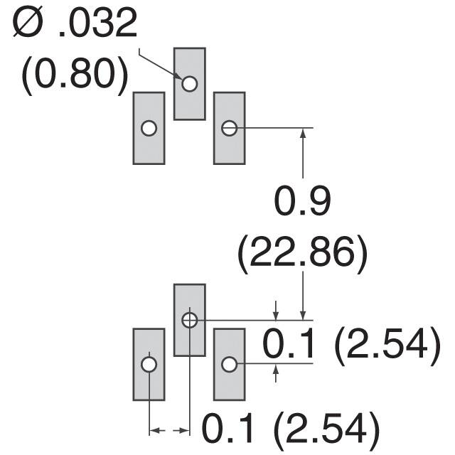


 工商网监
湘ICP备2023018690号
工商网监
湘ICP备2023018690号
