imp003 Breakout
The imp003 breakout board provides basic life support for the imp003 (Murata LBWA1ZV1CD). The
design includes power supply and GPIO breakout for the module, as well as the antenna, 32kHz
crystal (for maintaining the real‐time clock when offline), load switch for the radio power domain,
and required SPI Flash.
Set up
To set up an imp003 Breakout Board, please see this page.
�Pinout Chart
Click for larger version
Power
Power can be supplied using a USB Mini‐B cable from a USB Charger or a standard USB Port, though
the data lines are not connected to anything. Optionally, power can be provided through the VIN
header on the board edge.
imp003‐breakout includes footprint options for two different power supplies. By default, a 3.3V
LDO is populated as the system power supply. Using the LDO power supply, it is not recommended
that the supply voltage exceed 6V, for heat dissipation reasons.
Alternatively, footprints are included for a TI TPS62172 DC/DC buck power supply. If this option is
used in place of the LDO, the board can safely be operated from 3.3V to 17V DC.
Both power supply options include reverse‐voltage protection, which is especially helpful for any
application with removable batteries where they may be inserted backwards by the user.
�The USB connector should not be connected if power is provided through the VIN header on the
board edge.
Signals
All of the signals from the imp003 come out to a header. For descriptions of header pin functions,
please see the imp003 pin mux.
Hardware Design Files (Rev 1.1)
Schematics
Gerber Files
Bill of Materials
Altium Source Files
https://developer.electricimp.com/hardware/resources/reference‐designs/imp003breakout 4‐27‐18
�
很抱歉,暂时无法提供与“IMP003-BREAKOUT”相匹配的价格&库存,您可以联系我们找货
免费人工找货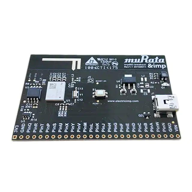


 工商网监
湘ICP备2023018690号
工商网监
湘ICP备2023018690号
