MPDRX004S DATA Sheet
1
DC-DC Converter DATA Sheet
MPDRX004S
1. Features
・ Ultra high-speed response is realized by using original ripple
detecting control.
・Up to 12A output current, non-isolated POL.
・ Wide adjustable output voltage range by connecting external
resistance (0.8V to 1.8V).
o
o
・Wide operating temperature(-40 C to +85 C).
・UVLO function, ON/OFF function, Output voltage sense function,
Over-current function and Over-temperature function are built in.
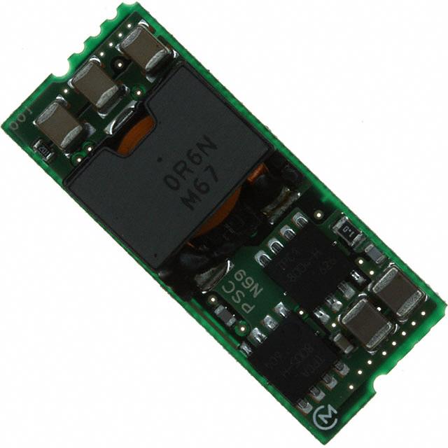
2. Appearance, Dimensions
33.0 +/- 0.2
①②③
8.0 max.
Top View
1.90
1.90
5.97
1.90
2.93
3 4
5 6
1.90
2.93
7 8
2.93
1.90
6.65
(実装後)
13.5 +/- 0.2
PSC
Pin detail
1.20
1.50
1.60
+0.20
-0.10
9 10
9.34
(1.45)
Bottom View
1 2
1.22
Marking
0.97
1.29
1.90
11
12
Hatching area :Lead Free Solder
(user soldering portion)
[unit:mm]
Tolerance:0.25mm
(1) MFG ID/ Pin No.1 marking
(2) Part No.
PSC
(3) Lot No.
①②③
①Production factory Mark
②Production Year
③Production Month(1,2,3,…9,O,N,D)
Note:
1. This datasheet is downloaded from the website of Murata Manufacturing co., ltd. Therefore, it’ s specifications are subject to change or our
products in it may be discontinued without advance notice. Please check with our sales representatives or product engineers before ordering.
2. This datasheet has only typical specifications because there is no space for detailed specifications. Therefore, please approve our product
specifications or transact the approval sheet for product specifications before ordering.
2010.11.15
�MPDRX004S DATA Sheet
2
Pin Number and Function
Pin No.
Symbol
1,2
Vin
3,4
GND
5,6
Vout
7,8
TRIM
9,10
SENSE
11,12
ON/OFF
Function
Input
GND
Output
Vout adjust control
Vout sense input
Remote ON/OFF
3. Block Diagram
Vout
Vin
5,6
1,2
SENSE
9,10
3,4
GND
11,12
7,8
Control Circuit
ON/OFF
4. Environmental Conditions
4 .1 Operating Temperature Range
4 .2 Storage Temperature Range
4 .3 Operating Humidity Range
4 .4 Storage Humidity Range
4 .5 Maximum Wet Bulb
5. Absolute Maximun Rating
5 .1 Input Voltage Range
5 .2 ON/OFF Pin Input Voltage Range
TRIM
-40 to +85 °C
(Temperature gradient ≤10°C/H)
-40 to +85 °C
(Temperature gradient ≤25°C /H)
20% to 85% (No condensation)
10% to 90% (No condensation)
39°C
7V to 14V
-0.3V to 5.5V
Note:
1. This datasheet is downloaded from the website of Murata Manufacturing co., ltd. Therefore, it’ s specifications are subject to change or our
products in it may be discontinued without advance notice. Please check with our sales representatives or product engineers before ordering.
2. This datasheet has only typical specifications because there is no space for detailed specifications. Therefore, please approve our product
specifications or transact the approval sheet for product specifications before ordering.
2010.11.15
�MPDRX004S DATA Sheet
3
6. Characteristics
o
6. 1 Electrical Characteristics (Ta=25 C)
Value
Item
Condition
Symbol
Unit
Min.
Typ.
Max.
7
12
14
V
Input Voltage Range
Vin
Rising UVLO Threshold
UVLOr
Vin Increasing
6.2
6.6
7.2
V
Falling UVLO Threshold
UVLOf
Vin Decreasing
6.0
6.3
6.7
V
Output Voltage
Adjustable Range
Vout
0.8
-
1.8
V
Output Voltage Tolerance
Vo tol
-2.5
-
+2.5
%Vo
Output Current
Iout
0
-
12
A
Ripple Voltage
Vrpl
-
15
40
-
25
50
-
30
-
µsec
-
50
-
mV
Vin =12V, Vout=1.8V, Iout=12A
-
89
-
%
Vin =12V, Vout=1.8V
-
600
-
Vin =12V, Vout=0.8V
-
300
-
Ttr
Transient Response
ΔVtr
Efficiency
EFF
Operating Frequency
Frq
Over Vin, Io, Temperature Range
Rset=0.5% tolerance
See the thermal derating curve
in section 6.2.
Vin =12V, Iout=12A
Vout=1.8V
BW=20MHz,
Vout=0.8V
Cout=100µF
Vin=12V,Vout=1.8V
Recovery
Iout=6⇔12A,
Time
di/dt=2A/µs,
Vout Deviation
Cout=100µF
mV(p_p)
kHz
ON/OFF pin is pulled up to Vin inside of the DC-DC Converter. If ON/OFF pin is
left open, the DC-DC Converter shall be “ON”. This pin will be pulled down to GND
inside the DC-DC Converter when OCP or OTP events occur. Please do NOT
connect this pin to Vin with low impedance line, so as not to damage the
converter..
If ON/OFF pin is connected to GND, the
0
0.7
V
DC-DC Converter shall be “OFF”.
ON/OFF pin High Voltage
VIH
ON/OFF pin Low Voltage
VIL
Short Circuit Protection
SCP
Vin=3.3V,
Reset, Followed by Auto-Recovery
13
21
-
OTP
Reset, Followed by Auto-Recovery
-
115
-
External Output Capacitor
Cout
When input voltage is ideal voltage
source
47
100
1000
µF
Rising Overshoot
Vover
-
0
+10
%
Output Delay
Td
Output Voltage 0-10% (remote on)
0.2
0.5
2
msec
Output Rise Time
Tr
Output Voltage 10-90%
1
4
8
msec
Over Temperature
Protection
A
o
C
Note:
1. This datasheet is downloaded from the website of Murata Manufacturing co., ltd. Therefore, it’ s specifications are subject to change or our
products in it may be discontinued without advance notice. Please check with our sales representatives or product engineers before ordering.
2. This datasheet has only typical specifications because there is no space for detailed specifications. Therefore, please approve our product
specifications or transact the approval sheet for product specifications before ordering.
2010.11.15
�MPDRX004S DATA Sheet
4
6. 2 Thermal Derating
MPDRX004S Thermal Derating
[ Vin=12V , Vout=1.8V ]
14
Output Current [A]
12
10
8
6
4
2
0
20
30
40
50
60
70
80
90
Ta [°C]
0m/s
0.5m/s
1.0m/s
2.0m/s
The above derating limits apply to this product soldered directly to 101.6*180mm*1.6mm PCB (double-sided,
with 70um copper). Any adjacent parts of high temperature may cause overheating. For reliable operation,
please ensure that the FET temperature of this product is maintained below 120°C and the inductor temperature
is below 106°C.
7. Operation information
7. 1 Adjusting the Output Voltage
The output voltage can be adjusted from 0.8V to 1.8V by connecting a resistor between
TRIM-pin(7,8Pin) to GND-pin(3,4Pin).
The following equation gives the required external-resistance value to adjust the output voltage to the
required Vout.
Internal circuit
MPDRX004S
Vout
6.8kΩ
TRIM pin
Rtrim =
5.1kΩ
Rtrim
5440
Vout - 0.8
- 5100
[ohm]
Error amp
Note:
1. This datasheet is downloaded from the website of Murata Manufacturing co., ltd. Therefore, it’ s specifications are subject to change or our
products in it may be discontinued without advance notice. Please check with our sales representatives or product engineers before ordering.
2. This datasheet has only typical specifications because there is no space for detailed specifications. Therefore, please approve our product
specifications or transact the approval sheet for product specifications before ordering.
2010.11.15
�MPDRX004S DATA Sheet
5
Vout [V]
Calculated Rtrim [ohm]
1.8
340
Rtrim example [ohm]
330
1.5
2671
2.4k+270
1.2
1.0
8500
22100
8.2k+300
22k+100
0.8
∞
Open
7. 2 ON/OFF Control
ON/OFF function
By using ON/OFF function, the operation of this product can be disabled without disconnection of input voltage.
Sequence of a power supply system and power-saving control can be easily achieved using this function.
ON/OFF Control Operation
When ON/OFF-pins(11,12pin) are left open
When ON/OFF-pins(11,12pin) are connected to GND
……
……
Output Voltage =ON
Output Voltage=OFF
MPDRX004S
11,12
3,4
example
GND
on/off
or
7. 3 Output voltage sensing
By connecting SENSE-pin to the load, output voltage drop in wiring shall be compensated.
Vout
MPDRX004S
SENSE
Load
GND
Please do NOT connect SENSE-pin to the output of LC filter that is set to the Vout line.
When using this way, this product will not operate properly.
Vout
MPDRX004S
SENSE
Load
GND
Note:
1. This datasheet is downloaded from the website of Murata Manufacturing co., ltd. Therefore, it’ s specifications are subject to change or our
products in it may be discontinued without advance notice. Please check with our sales representatives or product engineers before ordering.
2. This datasheet has only typical specifications because there is no space for detailed specifications. Therefore, please approve our product
specifications or transact the approval sheet for product specifications before ordering.
2010.11.15
�MPDRX004S DATA Sheet
6
7. 4 Input External capacitor
It is recommended to connect a ceramic capacitor or a low-impedance electrolytic capacitor of 22μF or more
at Vin terminal. Smaller input capacitor may leads to an unstable operation of this product caused by input
voltage fluctuation. Please check the proper operation of it on your product when smaller input capacitor is
used.
Using ceramic capacitors as input capacitor may cause an increase of output voltage, because input
ripple current flows through the external input capacitor and wiring resistance.
This phenomenon is affected by the position of external capacitors, the value of external capacitors and
voltage difference between Vin and Vout. Using low-impedance electrolytic capacitor will ease this problem.
Please check the proper operation of it on your product when ceramic input capacitor is used.
MPDRX004S
Vin
Cin
Vout
Ripple current
Rw×Irpl appears as additional
output ripple voltage.
Rw
Wiring resistance
7. 5 Output External capacitor
Ceramic capacitors are recommended as output external capacitor.
Using ceramic capacitors, small output variation and small ripple voltage are realized.
Output capacitor should be within 47uF to 1000uF. Output capacitor shall be placed near the
output terminal. When using plural capacitors, please make sure to place a capacitor of at least
47μF near the output terminal, and place other capacitors near the load.
When using LC output filter, please make sure to place a capacitor of at least 47μF near the output terminal.
8. Reliability
8 .1 Humidity
According to JIS-C-0022.
40 土2°C, 90 to 95%RH, 100 hours. Leave for 4 hours at room temperature.
No damage in appearance and no deviation from electrical characteristics (section 6. 1).
8 .2 Temperature Cycles
Repeat cycle 5 times. Leave 2 hours at room temp.
No damage in appearance and no deviation from electrical characteristics (section 6. 1).
Step
Condition
Time
1
-40°C±3°C
30 minutes
2
Room Temp
5-10 minutes
3
+85°C±2°C
30 minutes
4
Room Temp.
5-10 minutes
8 .3 Vibration
10 to 55Hz, 1.5mm amplitude (1minute cycle), 1 hour for each of X, Y, Z directions.
No damage in appearance and no deviation from electrical characteristics (section 6. 1).
8 .4 Mechanical Shock
20G, 1 time for each X, Y, Z directions.
No damage in appearance and no deviation from electrical characteristics (section 6. 1).
Note:
1. This datasheet is downloaded from the website of Murata Manufacturing co., ltd. Therefore, it’ s specifications are subject to change or our
products in it may be discontinued without advance notice. Please check with our sales representatives or product engineers before ordering.
2. This datasheet has only typical specifications because there is no space for detailed specifications. Therefore, please approve our product
specifications or transact the approval sheet for product specifications before ordering.
2010.11.15
�MPDRX004S DATA Sheet
7
9. Test Circuit
Using the following test circuit, the initial values under section 6.1 shall be met.
9.1. General Measure Circuit
Vin
+
Vin
Cin: 22μF
Vout
1,2
5,6
MPDRX004S
ON/OF
F
9,10
7,8
11,12
SENSE
RL
TRIM
3,4
Open=ON
Short=OFF
Cout: 100μF
Rset
GND
: 22µF/16V
(GRM32ER71C226KE15L, Murata)
(Ceramic Capacitor)
Cout : 100µF/6.3V (GRM32EB30J107ME16L, Murata)
(Ceramic Capacitor)
Cin
9.2. Ripple Noise Measurement Circuit
Note:
1. This datasheet is downloaded from the website of Murata Manufacturing co., ltd. Therefore, it’ s specifications are subject to change or our
products in it may be discontinued without advance notice. Please check with our sales representatives or product engineers before ordering.
2. This datasheet has only typical specifications because there is no space for detailed specifications. Therefore, please approve our product
specifications or transact the approval sheet for product specifications before ordering.
2010.11.15
�MPDRX004S DATA Sheet
8
10. Packaging Specification
10.1. Emboss Tape Dimensions
10.2. Real Dimension
Note:
1. This datasheet is downloaded from the website of Murata Manufacturing co., ltd. Therefore, it’ s specifications are subject to change or our
products in it may be discontinued without advance notice. Please check with our sales representatives or product engineers before ordering.
2. This datasheet has only typical specifications because there is no space for detailed specifications. Therefore, please approve our product
specifications or transact the approval sheet for product specifications before ordering.
2010.11.15
�MPDRX004S DATA Sheet
9
10.3. Taping Specification
10. 4 Note
1. The adhesive strength of the protective tape must be within 0.1-1N.
2. Each reel contains 200pcs.
3. No vacant pocket in “Module on tape” section.
4. The reel is labeled with customer part number, Murata part number and quantity.
5. The color of reel is not specified.
11. Production factory
Komatsu Murata Mfg.Co., Ltd.
Kanazu Murata Mfg. Co., Ltd.
Wakura Murata Mfg. Co., Ltd.
Note:
1. This datasheet is downloaded from the website of Murata Manufacturing co., ltd. Therefore, it’ s specifications are subject to change or our
products in it may be discontinued without advance notice. Please check with our sales representatives or product engineers before ordering.
2. This datasheet has only typical specifications because there is no space for detailed specifications. Therefore, please approve our product
specifications or transact the approval sheet for product specifications before ordering.
2010.11.15
�MPDRX004S DATA Sheet
10
12. Typical Characteristics Data
12. 1 Load Transient Response
Our original ripple-detective control method achieves much better load transient responses.
Vin=12V, Vo=1.8V, Io=6A ->12A, di/dt=2A/μs, Cout=100μF(Ceramic)
50mV/div
20us/div
Fig. 12-1. Load Transient Response
12. 2 Output Impedance characteristics
Our original ripple-detective control method achieves very low output impedance in wide
frequency range.
Conventional PMW Product's Output
Impedance
100
100
80
80
Zo [mohm]
Zo [mohm]
MPDRX004S Output Impedance
Vo=1.8V
60
40
40
20
20
0
0.01
60
0.1
1
10
100
Frequency [kHz]
Fig. 12-2-1. Output Impedance of MPDRX004S
0
0.01
0.1
1
10
100
Frequency [kHz]
Fig. 12-2-2. Output Impedance of conventional product
Note:
1. This datasheet is downloaded from the website of Murata Manufacturing co., ltd. Therefore, it’ s specifications are subject to change or our
products in it may be discontinued without advance notice. Please check with our sales representatives or product engineers before ordering.
2. This datasheet has only typical specifications because there is no space for detailed specifications. Therefore, please approve our product
specifications or transact the approval sheet for product specifications before ordering.
2010.11.15
�MPDRX004S DATA Sheet
11
12. 3 Other electrical characteristics
12. 3. 1 Vout=1.8V
o
1.820
94
1.815
92
1.810
90
Efficiency (%)
Output Voltage(V)
(Ta=25 C, Cin=GRM32ER71C226KE15L, Cout=GRM32EB30J107ME16L, Rtrim=340Ω)
1.805
1.800
1.795
88
86
84
1.790
82
1.785
80
1.780
78
0
2
4
6
8
10
12
0
2
Io(A)
Vin=7V
4
6
8
10
12
Io(A)
Vin=12V
Vin=14V
Vin=7V
Fig. 12-3-1. Output Voltage v.s. Output Current
Vin=12V
Vin=14V
Fig. 12-3-2. Efficiency v.s. Output Current
30
Ripple Voltage (V)
25
20
15
10
5
0
0
2
4
6
8
10
12
Io(A)
Vin=7V
Vin=12V
Vin=14V
Fig. 12-3-3. Ripple Voltage v.s. Output Current
Note:
1. This datasheet is downloaded from the website of Murata Manufacturing co., ltd. Therefore, it’ s specifications are subject to change or our
products in it may be discontinued without advance notice. Please check with our sales representatives or product engineers before ordering.
2. This datasheet has only typical specifications because there is no space for detailed specifications. Therefore, please approve our product
specifications or transact the approval sheet for product specifications before ordering.
2010.11.15
�MPDRX004S DATA Sheet
12
12. 3. 2 Vout=1.2V
o
1.220
94
1.215
92
1.210
90
Efficiency (%)
Output Voltage(V)
(Ta=25 C, Cin=GRM32ER71C226KE15L, Cout=GRM32EB30J107ME16L, Rtrim=8.5kΩ)
1.205
1.200
1.195
88
86
84
1.190
82
1.185
80
1.180
78
0
2
4
6
8
10
12
0
2
Io(A)
Vin=7V
4
6
8
10
12
Io(A)
Vin=12V
Vin=14V
Vin=7V
Fig. 12-3-4. Output Voltage v.s. Output Current
Vin=12V
Vin=14V
Fig. 12-3-5. Efficiency v.s. Output Current
30
Ripple Voltage (V)
25
20
15
10
5
0
0
2
4
6
8
10
12
Io(A)
Vin=7V
Vin=12V
Vin=14V
Fig. 12-3-6. Ripple Voltage v.s. Output Current
Note:
1. This datasheet is downloaded from the website of Murata Manufacturing co., ltd. Therefore, it’ s specifications are subject to change or our
products in it may be discontinued without advance notice. Please check with our sales representatives or product engineers before ordering.
2. This datasheet has only typical specifications because there is no space for detailed specifications. Therefore, please approve our product
specifications or transact the approval sheet for product specifications before ordering.
2010.11.15
�MPDRX004S DATA Sheet
13
13. Mounting Condition
13. 1 PCB Land Pattern Recommendation
7.54
4.83
4.83
4.83
7.87
10.9
10.3
0.635
Unit:mm
29.9
Recommended land size 4mm × 2.5mm
13. 2 Recommended Soldering Conditions
Reflow Soldering
This product is RoHS compatible. The following profile is recommended for the reflow of this
product using Pb-free solder paste (Sn-Ag-Cu).
Reflow Soldering Profile
Method
Soldering temperature
Soldering time
Preheating
Time
: Full convection reflow soldering
: 245°C +0/-5°C (Parts surface temperature)
: 20 to 60 seconds max. (Over 220°C)
: 60 to 150 seconds (150-200°C)
:1 time
240°C
Part’s surface temperature[ºC]
220°C
200°C
(20~62seconds)
100°C
)
(60~150seconds)
Times
※Do not vibrate for the products on reflow.
Please need to take care temperature control because mounted parts may come off if the product are
left under the high temperature.
Do not reflow DC-DC converter as follows, because DC-DC converter may fall down from a substrate
during reflowing.
Substrate
Note:
DC-DC Converter
1. This datasheet is downloaded from the website of Murata Manufacturing co., ltd. Therefore, it’ s specifications are subject to change or our
products in it may be discontinued without advance notice. Please check with our sales representatives or product engineers before ordering.
2. This datasheet has only typical specifications because there is no space for detailed specifications. Therefore, please approve our product
specifications or transact the approval sheet for product specifications before ordering.
2010.11.15
�MPDRX004S DATA Sheet
14
14. Notice
14. 1.
Both input-side and output side, please make the wiring loop between plus and minus as small as possible.
The influence of a leakage inductance can be reduced.
14. 2.
Please make the power line pattern as wide and short as possible.
The Following figure is an example of recommendable PCB design.
Vout
Output Capacitor
GND
Input
Vin
14. 3.
This product should not be operated in parallel or in series.
14. 4.
Please do not use a connector or a socket to connect this product to your product.
The electric characteristics may be deteriorated by the influence of contact resistance.
14. 5.
Be sure to provide an appropriate fail-safe function on your product to prevent secondary damage
that may be caused due to abnormal functional or failure of this product.
14. 6.
Inrush current protection is not a feature of this product.
14. 7.
Be sure not to warp your PCB over 90μm.
If not, the parts on the backside of this device touch on your PCB, and that may lead to cracks of the
backside parts or reliability deterioration of this device.
Note:
1. This datasheet is downloaded from the website of Murata Manufacturing co., ltd. Therefore, it’ s specifications are subject to change or our
products in it may be discontinued without advance notice. Please check with our sales representatives or product engineers before ordering.
2. This datasheet has only typical specifications because there is no space for detailed specifications. Therefore, please approve our product
specifications or transact the approval sheet for product specifications before ordering.
2010.11.15
�MPDRX004S DATA Sheet
15
14. 8.
Please connect the input terminals with the correct polarity. If an error in polarity connection is made this
product may be damaged. If this product is damaged internally, an elevated input current may flow, and so
this product may exhibit an abnormal temperature rise, or your product may be damaged.
Please add a diode and fuse per the following diagram to protect them.
fuse
+
+
+
diode
IN
-
OUT
Load
-
※Please select diode and fuse after confirming the operation of your product.
14. 9.
Cleaning
Please use no-clean type flux and do not wash this product.
14. 10.
Storage
14. 10. 1. This product should be treated as MSL2 product when it is reflowed according to recommended
soldering conditions described in section 13. 2. .
This product can be stored for up to 1 year at below 30°C/60%R.H., without requiring an
additional baking process.
If stored for over 1 year, baking of this product before soldering is recommended.
The recommended baking condition of individual products is 125±5°C / 24 hours.
If products are baked in the manufacturer’s tray or in manufacturer’s tape, 40±5°C/5%/192 hours
is recommended.
Please avoid dampness and heat or locations where temperatures may vary widely to avoid
Possible water condensation on the product. Exposure to such environments may degrade the
performance and/or the reliability of the product.
If the product must be stored for a longer time than 1 year it is recommend that solder ability be
tested regularly to confirm material degradation has not occurred.
14. 10. 2 Please do not store this product in places such as :
A dusty place, a place exposed directly to sea breeze, or in an atmosphere
containing corrosive gas (Cl2,NH3,SO2,NOX and so on).
Note:
1. This datasheet is downloaded from the website of Murata Manufacturing co., ltd. Therefore, it’ s specifications are subject to change or our
products in it may be discontinued without advance notice. Please check with our sales representatives or product engineers before ordering.
2. This datasheet has only typical specifications because there is no space for detailed specifications. Therefore, please approve our product
specifications or transact the approval sheet for product specifications before ordering.
2010.11.15
�MPDRX004S DATA Sheet
16
14. 11 Operational Environment and Operational Conditions
14. 11. 1. Operational Environment
This product is not water-, chemical- or corrosion-proof.
In order to prevent leakage of electricity and abnormal temperature rise of the product, do not operate
under the following environmental conditions:
(1) An atmosphere containing corrosive gas (Cl2, NH3, SO2, NOX and so on)
(2) A high-dust environment
(3) Under the exposure of direct sunlight
(4) A location where the likelihood of exposure to water or water condensation exists.
(5) A location exposed to ocean air
(6) Any locations similar to the above
14. 11. 2. Operational Conditions
Please use this product within specified values (power supply, temperature, input, output and load
condition, and so on). If the product is exposed to conditions outside of the specified values reliability of
the product may be adversely effected.
14. 11. 3. Note prior to use
Diminished reliability and/ or failure may result if the product is exposed to a high-level static charge,
over-rated voltage or reverse voltage. Please avoid the following conditions be avoided prior to use of
the product:
(1) Supply of power outside of rated values (see section 8)
(2) Supply of reverse power or inadequate connection of a 0 V(DC)line
(3) Electrostatic discharge from production line and/ or operator
(4) Electrification of the product from electrostatic induction
(5) Excessive mechanical shock
14. 12. Transportation
Murata recommends that when transporting this product, it be packed so as to avoid damage by
mechanical
vibration or exposure to adverse conditions such as ocean air, high humidity. It is additionally
recommended
that appropriate instructions and guidelines be communicated to carriers to prevent exposure to these
same
conditions.
!
Note
1. Murata recommends that customers ensure that the evaluation and testing of these devices are completed
withthis product actually assembled on their product.
2. Please contact our main sales office or nearby sales office before using our products for the applications
listed below which require especially high reliability for the prevention of defects which might directly
cause damage to the third party’s life, body or property or this products for any other applications that
described in the above.
①Aircraft equipment
②Aerospace equipment
③Undersea equipment
④Power plant control equipment
⑤Medical equipment
⑥Transportation equipment (vehicles, trains, ships, etc.)
⑦Traffic signal equipment
⑧Disaster prevention /crime prevention equipment
⑨Data-processing equipment
⑩Application of similar complexity and/or reliability requirements to the applications listed in the above.
3.
This catalog is indicated in March 2006. About the written contents, since changing without a preliminary
announcement for improvement and supply are sometimes stopped, please confirm in case of ordering.
If written contents are unknown, please ask to our main sales office or nearby sales office.
Note:
1. This datasheet is downloaded from the website of Murata Manufacturing co., ltd. Therefore, it’ s specifications are subject to change or our
products in it may be discontinued without advance notice. Please check with our sales representatives or product engineers before ordering.
2. This datasheet has only typical specifications because there is no space for detailed specifications. Therefore, please approve our product
specifications or transact the approval sheet for product specifications before ordering.
2010.11.15
�


 工商网监
湘ICP备2023018690号
工商网监
湘ICP备2023018690号
