Automation Controls Catalog
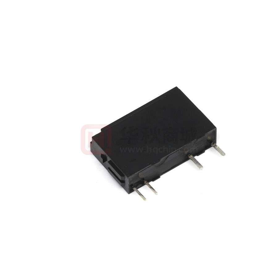
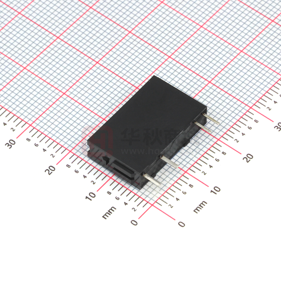
1 Form A 5A
slim power relay
complies with IEC61010
reinforced insulation
FEATURES
Protective construction: Sealed type (RTIII)
1. High density mounting
5mm(W) 20mm(L) 12.5mm(H)
2. Low operating power
Rated operating power: 110mW
3. Complies with IEC61010 reinforced
insulation standards
4. Long insulation distance
• Clearance: 5.29mm
Creepage distance: 5.35mm
(Between contact and coil)
• 3,000 V dielectric strength and
6,000V surge breakdown voltage
5. Complies with standard for
hazardous location (ANSI/ISA
12.12.01)
PA-N RELAYS
TYPICAL APPLICATIONS
1. Output relays for programmable
controllers and temperature
controllers
2. Industrial equipment, office
equipment
3. Measuring devices and test
equipment
ORDERING INFORMATION
APAN 3 1
Contact arrangement
3: 1 Form A
(Bifurcated)
Terminals and rated operating power
1: PC board terminal(110mW)
Rated coil voltage
(DC)
03: 3V, 4H: 4.5V, 05: 5V, 06: 6V
09: 9V, 12: 12V, 18: 18V, 24: 24V
TYPES
Contact arrangement
1 Form A
Rated coil voltage
Part No.
3 V DC
APAN3103
4.5 V DC
APAN314H
5 V DC
APAN3105
6 V DC
APAN3106
9 V DC
APAN3109
12 V DC
APAN3112
18 V DC
APAN3118
24 V DC
APAN3124
Standard packing
Carton (Tube)
Outer carton
25 piecies
1,000 piecies
* Terminal sockets available.
2019.04
industrial.panasonic.com/ac/e/
ー1ー
c Panasonic Corporation 2019
ASCTB368E 201904
�PA-N (APAN3)
RATING
1.Coil data
•�Operating characteristics such as ‘Operate voltage’ and ‘Release voltage’ are influenced by mounting conditions, ambient temperature,
etc.Therefore, please use the relay within ± 5% of rated coil voltage.
•‘Initial’ means the condition of products at the time of delivery.
Rated coil
voltage
Operate voltage
(at 20°C)
Release voltage
(at 20°C)
Rated operating
current
[10%] (at 20°C)
Coil resistance
[±10%] (at 20°C)
3 V DC
36.7 mA
82 Ω
4.5 V DC
24.4 mA
184 Ω
22.0 mA
227 Ω
18.3 mA
327 Ω
12.2 mA
736 Ω
5 V DC
70%V or less of
rated voltage*
(Initial)
6 V DC
9 V DC
12 V DC
5%V or more of
rated voltage*
(Initial)
9.2 mA
1,309 Ω
18 V DC
6.1 mA
2,945 Ω
24 V DC
4.6 mA
5,236 Ω
Rated operating
power
Max. allowable voltage
(at 20°C)
110 mW
120%V of
rated voltage
Note: *Pulse drive (JIS C 5442)
2.Specifications
Item
Contact arrangement
Contact data
Contact resistance (initial)
Max. 30 mΩ (by voltage drop 6 V DC 1A)
Contact material
AgNi type + Au
Contact rating (resistive)
5 A 250 V AC, 5 A 30 V DC
Max. switching power (resistive) 1,250 VA, 150 W
Max. switching voltage
250 V (AC), 110 V (DC) (0.4 A)
Max. switching current
5 A (AC, DC)
Min. switching capacity
(reference value)*1
100 µA 100 mV DC
Insulation resistance (initial)
Dielectric strength
(initial)
Surge breakdown
voltage (initial)*2
Time characteristics
(initial)
Shock resistance
Vibration resistance
Specifications
1 Form A (bifurcated)
Min. 1,000MΩ (at 500V DC)
Measurement at same location as “Breakdown voltage” section.
Between open contacts
1,000 Vrms for 1min. (detection current: 10mA.)
Between contact and coil
3,000 Vrms for 1min. (detection current: 10mA.)
Between contacts and coil
6,000 V
Operate time
Max. 10 ms (at rated coil voltage at 20°C, without bounce)
Release time
Max. 5 ms (at rated coil voltage at 20°C, without bounce, without diode)
Functional
Min. 147 m/s2 (half-wave pulse of sine wave: 11 ms; detection time: 10 µs.)
Destructive
Min. 980 m/s2 (half-wave pulse of sine wave: 6 ms.)
Functional
10 to 55 Hz (at double amplitude of 2.5 mm, detection time: 10 µs.)
Destructive
10 to 55 Hz (at double amplitude of 3.5 mm)
Expected life
Mechanical
Min. 2×10⁷ (at 180 times/min.)
Conditions
Condition for usage, transport
and storage*3
Ambient temperature: -40°C to +90°C
Humidity: 5 to 85% R.H. (not freezing and condensing at low temperature)
Approx. 3 g
Unit weight
Notes: *1. This value can change due to the switching frequency, environmental conditions, and desired reliability level, therefore it is recommended to check this with the actual
load.
*2. Wave is standard shock voltage of ±1.2×50µs according to JEC-212-1981
*3. The upper limit of the ambient temperature is the maximum temperature that can satisfy the coil temperature rise value. Refer to Usage, transport and storage conditions
in NOTES.
3.Expected electrical life
Conditions: Resistive load, at 20 times/min.
Type
1 Form A
Switching capacity
Number of operations
3 A 250 V AC
Min. 105
3 A 30 V DC
Min. 105
5 A 250 V AC
Min. 5×10⁴
(at 6 times/min, ON:OFF = 1 s:9 s)
5 A 30 V AC
Min. 5×10⁴
Panasonic Corporation Electromechanical Control Business Division
industrial.panasonic.com/ac/e/
ー2ー
c Panasonic Corporation 2019
ASCTB368E 201904
�PA-N (APAN3)
REFERENCE DATA
1. Max. switching capacity
2. Life curve
3. Coil temperature rise
Tested sample: APAN3124, 6 pcs.
Measured portion: Inside the coil
Ambient temperature: 20°C, 90°C (No contact current)
10
DC resistive load
1
0.4
35
30V DC
resistive load
100
50
40
30
20
Temperature rise (°C)
No. of operations (×10 4)
Contact current (A)
5
40
250V AC
resistive load
AC resistive load
250V AC
(cosφ = 0.4)
30V DC
(L/R = 7ms)
10
5
30
25
20°C 5A
20°C 3A
20°C 0A
20
15
90°C 0A
10
5
0.1
1
10
100
1
0.1
1,000
Contact voltage (V)
5
10
Drop-out
voltage
10
Pick-up voltage
0
60
80 100
Ambient
temperature (°C)
[m/s2]
130
140
150
Deenergized condition
Energized condition
800
600
400
X
7.0
6.0
0
Max.
Ave.
Min.
4.0
3.0
Release time
0
70
80
90
100
Z
200
Operate time
5.0
1.0
ー30
120
Y
1,000
8.0
2.0
ー20
DIMENSIONS (mm)
110
Tested sample: APAN3124, 6 pcs.
9.0
20 40
100
6. Malfunctional shock
10.0
30
20
0
90
Coil applied voltage (%V)
Tested sample: APAN3124, 20 pcs.
Measured direction: Upright
Operate & release time (ms)
Rate of change (%)
3
5. Operate & release time
Tested sample: APAN3124, 6 pcs.
ー10
1
Contact current (A)
4. Ambient temperature characteristics
ー60 ー40 ー20
0.5
X’ Z’
Y’
Z’
Max.
Ave.
Min.
110
120
Coil applied voltage (%V)
Z
Y
X
Y’
X’
130
CAD The CAD data of the products with a “CAD” mark can be downloaded from our Website.
External dimensions
CAD
PC board pattern (Bottom view)
1dia. 1dia.
1.2dia.
1.2dia.
1.2
8.8
1.3
6
4.8
2.9
3.5 12.5(Max.12.8)
0.3
0.5
5
2.54
2.54
Tolerance ±0.1
0.5
10.16
20
5.08
0.8
1.1
1.2
0.25
Schematic (Bottom view)
General tolerance ±0.3
Panasonic Corporation Electromechanical Control Business Division
industrial.panasonic.com/ac/e/
10.16 5.08
ー3ー
1 2
c Panasonic Corporation 2019
5
6
ASCTB368E 201904
�PA-N (APAN3)
SAFETY STANDARDS
UL/C-UL (Recognized)
File No.
E43149
TÜV (Certified)
Contact ratings
Cycles
Temp.
5 A 250 V AC resistive
5 A 250 V AC resistive
5 A 30 V DC general use
5 A 30V DC, 3 A 250 V AC general use
3 A 250 V AC resistive
3 A 30 V DC general use
B300, R300 pilot duty
5×10⁴
104
5×10⁴
104
105
105
6×10³
40°C
90°C
40°C
90°C
40°C
40°C
40°C
File No.
Contact ratings
B18 03 13461 368 5 A 250 V AC (cosφ =1.0)
5 A 250 V AC (cosφ =1.0)
5 A 30 V DC (0 ms)
5 A 30 V DC (0 ms)
3 A 250 V AC (cosφ =1.0)
3 A 30 V DC (0 ms)
Cycles
Temp.
5×10⁴
104
5×10⁴
104
105
105
40°C
90°C
40°C
90°C
40°C
40°C
E479891 Class I, division 2, groups A, B, C, D hazardous location
(ANSI/ISA 12.12.01-2015, CAN/CSA C22.2 No.213-15)
Insulation distance (between contact and coil)
• UL/C-UL: Clearance distance: 5.29 mm , Creepage distance: 5.35 mm .
• TÜV: Clearance distance: 5.29 mm , Creepage distance: 5.35 mm .
NOTES
1. For cautions for use, please read “GENERAL
APPLICATION GUIDELINES”.
2. If it includes ripple, the ripple factor should be less
than 5%.
3. Specification values for pick-up and drop-out
voltages are for the relay mounting with its terminals
below.
Tested sample: APAN3124, 6 pcs.
Ambient temperature: 20°C
Measured direction: 6 direction
4. When mounting the relays within 1 mm please notice
the condition below.
1) Mount the relays in the same direction.
Within 1mm
Tested sample: APAN3124, 6 pcs.
Ambient temperature: 20゚C
Measured direction: 6 directions
100
2) Coil terminals (Terminal No. 1 & 2)
polarity should be arranged in the same direction.
90
Voltage (%V)
80
70
Pick-up voltage
Max.
60
Ave.
Min.
50
40
30
20
Drop-out voltage
Max.
Ave.
Min.
10
0
Top
Mounting direction
Bottom
Please refer to "the latest product specifications"
when designing your product.
•Requests to customers:
https://industrial.panasonic.com/ac/e/salespolicies/
Panasonic Corporation Electromechanical Control Business Division
industrial.panasonic.com/ac/e/
ー4ー
c Panasonic Corporation 2019
ASCTB368E 201904
�PA-N RELAYS
TERMINAL SOCKETS
ACCESSORIES
TYPES
Product name
Standard type terminal socket
Self clinching type terminal socket
Standard type
terminal socket
Self clinching type
terminal socket
DIMENSIONS (mm inch)
CAD The CAD data of the products with a “CAD” mark can be downloaded from our Website.
Standard type terminal socket
External dimensions
CAD
1
Part No.
PA1a-PS
PA1a-PS-H
2
3
4
5
Self clinching type terminal socket
External dimensions
CAD
5+0.2
–0.6
.197+.008
–.024
6
1
2
22.6±0.6
.890±.024
4
.157
0.5
.020
2.54
.100
6.35
.250
3
4
5
5+0.2
–0.6
.197+.008
–.024
6
22.6±0.6
.890±.024
0.8
.031
3.81
.150
9±0.6
.354±.024
9±0.6
.354±.024
5.3±0.6
.209±.024
5.3±0.6
.209±.024
(0.3)
(.012)
5.08
.200
3.9
1±0.25
.154
.039±.010
1.23
.048
0.25
.010
1.23
.048
0.8
.031
0.5
.020
2.54
.100
6.35
.250
3.81
.150
(0.3)
(.012)
5.08
.200
General tolerance:±0.3 ±.012
General tolerance:±0.3 ±.012
PC board pattern (Bottom view)
PC board pattern (Bottom view)
1.0 dia.
.039 dia.
1.0 dia.
.039 dia.
2.54
.100
10.16
.400
1.2 dia.
.047 dia.
1.2 dia.
.047 dia.
1.3±0.15
.051±.006
0.8±0.25 dia. 1.2±0.05 dia.
.031±.010 dia. .047±.002 dia.
0.8±0.25 dia.
1.2±0.05 dia.
.031±.010 dia. .047±.002 dia.
5.08
.200
2.54
.100
Tolerance: ±0.1 ±.004
10.16
.400
5.08
.200
Tolerance: ±0.1 ±.004
INSTALLING AND REMOVING
Installing and removing the relay
1) Firmly insert the relay into the socket
with the terminals going in the direction of
the blade receptacles.
2) The relay can be easily removed using
the removal key (APA801).
(1) Insert the removal key into the socket
slots.
(2) Pull the removal key up to remove the
relay.
Panasonic Corporation Electromechanical Control Business Division
industrial.panasonic.com/ac/e/
ー5ー
(3) Slide the removal key off of the relay.
© Panasonic Corporation 2019
ASCTB373E 201903
�GUIDELINES FOR POWER RELAYS AND HIGH-CAPACITY DC CUT OFF RELAYS USAGE
For cautions for use, please read “GUIDELINES FOR RELAY USAGE”.
https://industrial.panasonic.com/ac/e/control/relay/cautions_use/index.jsp
Precautions for Coil Input
Long term current carrying
A circuit that will be carrying a current continuously for long periods
without relay switching operation. (circuits for emergency lamps, alarm
devices and error inspection that, for example, revert only during
malfunction and output warnings with form B contacts) Continuous,
long-term current to the coil will facilitate deterioration of coil insulation
and characteristics due to heating of the coil itself.
For circuits such as these, please use a magnetic-hold type latching
relay. If you need to use a single stable relay, use a sealed type relay
that is not easily affected by ambient conditions and make a failsafe
circuit design that considers the possibility of contact failure or
disconnection.
DC Coil operating power
Steady state DC current should be applied to the coil. The wave form
should be rectangular. If it includes ripple, the ripple factor should be
less than 5%.
However, please check with the actual circuit since the electrical
characteristics may vary. The rated coil voltage should be applied to
the coil and the set/reset pulse time of latching type relay differs for
each relays, please refer to the relay's individual specifications.
Maximum allowable voltage and temperature rise
Proper usage requires that the rated coil voltage be impressed on the
coil. Note, however, that if a voltage greater than or equal to the
maximum continuous voltage is impressed on the coil, the coil may
burn or its layers short due to the temperature rise. Furthermore, do
not exceed the usable ambient temperature range listed in the catalog.
Operate voltage change due to coil temperature rise
(Hot start)
In DC relays, after continuous passage of current in the coil, if the
current is turned OFF, then immediately turned ON again, due to the
temperature rise in the coil, the pick-up voltage will become somewhat
higher. Also, it will be the same as using it in a higher temperature
atmosphere. The resistance/temperature relationship for copper wire
is about 0.4% for 1°C, and with this ratio the coil resistance increases.
That is, in order to operate of the relay, it is necessary that the voltage
be higher than the pick-up voltage and the pick-up voltage rises in
accordance with the increase in the resistance value. However, for
some polarized relays, this rate of change is considerably smaller.
Coil connection
When connecting coils of polarized relays, please check coil polarity
(+,-) at the internal connection diagram (Schematic). If any wrong
connection is made, it may cause unexpected malfunction, like
abnormal heat, fire and so on, and circuit do not work. Avoid
impressing voltages to the set coil and reset coil at the same time.
Ambient Environment
Dew condensation
Usage, Transport, and Storage Conditions
Condensation occurs when the ambient temperature drops
suddenly from a high temperature and humidity, or the relay is
suddenly transferred from a low ambient temperature to a high
temperature and humidity. Condensation causes the failures like
insulation deterioration, wire disconnection and rust etc.
Panasonic Corporation does not guarantee the failures caused
by condensation.
The heat conduction by the equipment may accelerate the
cooling of device itself, and the condensation may occur.
Please conduct product evaluations in the worst condition of
the actual usage. (Special attention should be paid when high
temperature heating parts are close to the device. Also please
consider the condensation may occur inside of the device.)
During usage, storage, or transportation, avoid locations
subjected to direct sunlight and maintain normal temperature,
humidity and pressure conditions.
Temperature/Humidity/Pressure
When transporting or storing relays while they are tube
packaged, there are cases the temperature may differ from the
allowable range. In this case be sure to check the individual
specifications. Also allowable humidity level is influenced by
temperature, please check charts shown below and use relays
within mentioned conditions. (Allowable temperature values
differ for each relays, please refer to the relay's individual
specifications.)
Icing
Condensation or other moisture may freeze on relays when the
temperature become lower than 0°C.This icing causes the sticking of
movable portion, the operation delay and the contact conduction failure
etc. Panasonic Corporation does not guarantee the failures caused by
the icing.
The heat conduction by the equipment may accelerate the cooling of
relay itself and the icing may occur. Please conduct product
evaluations in the worst condition of the actual usage.
Low temperature and low humidity
The plastic becomes brittle if the switch is exposed to a low
temperature, low humidity environment for long periods of time.
High temperature and high humidity
Storage for extended periods of time (including transportation periods)
at high temperature or high humidity levels or in atmospheres with
organic gases or sulfide gases may cause a sulfide film or oxide film to
form on the surfaces of the contacts and/or it may interfere with the
functions. Check out the atmosphere in which the units are to be
stored and transported.
1) Temperature:
The tolerance temperature range differs for each relays,
please refer to the relay’s individual specifications
2) Humidity:
5 to 85 % RH
3) Pressure:
86 to 106 kPa
Humidity, %R.H.
85
Allowable range
(Avoid icing
when used at
temperatures
lower than 0°
C)
5
–40
(Avoid
condensation
when used at
temperatures
higher than
0°
C)
0
Ambient temperature, °
C
85
Panasonic Corporation Electromechanical Control Business Division
industrial.panasonic.com/ac/e/
ー6ー
c Panasonic Corporation 2019
ASCTB412E 201903
�GUIDELINES FOR POWER RELAYS AND HIGH-CAPACITY DC CUT OFF RELAYS USAGE
Package
In terms of the packing format used, make every effort to keep the
effects of moisture, organic gases and sulfide gases to the absolute
minimum.
Silicon
When a source of silicone substances (silicone rubber, silicone oil,
silicone coating materials and silicone filling materials etc.) is used
around the relay, the silicone gas (low molecular siloxane etc.) may be
produced.
This silicone gas may penetrate into the inside of the relay. When the
relay is kept and used in this condition, silicone compound may adhere
to the relay contacts which may cause the contact failure. Do not use
any sources of silicone gas around the relay (Including plastic seal
types).
NOx Generation
When relay is used in an atmosphere high in humidity to switch a load
which easily produces an arc, the NOx created by the arc and the
water absorbed from outside the relay combine to produce nitric acid.
This corrodes the internal metal parts and adversely affects operation.
Avoid use at an ambient humidity of 85%RH or higher (at 20°C). If use
at high humidity is unavoidable, please contact our sales
representative.
Others
Cleaning
1) �Although the environmentally sealed type relay (plastic sealed type,
etc.) can be cleaned, avoid immersing the relay into cold liquid (such
as cleaning solvent) immediately after soldering. Doing so may
deteriorate the sealing performance.
2) �Cleaning with the boiling method is recommended(The temperature
of cleaning liquid should be 40°C or lower ).
Avoid ultrasonic cleaning on relays. Use of ultrasonic cleaning may
cause breaks in the coil or slight sticking of the contacts due to
ultrasonic energy.
Please refer to "the latest product specifications"
when designing your product.
•Requests to customers:
https://industrial.panasonic.com/ac/e/salespolicies/
Panasonic Corporation Electromechanical Control Business Division
industrial.panasonic.com/ac/e/
ー7ー
c Panasonic Corporation 2019
ASCTB412E 201903
�Please contact ..........
Panasonic Corporation
Electromechanical Control Business Division
1006, Oaza kadoma, kadoma-shi, Osaka 571-8506, japan
industral.panasonic.com/ac/e/
©Panasonic Corporation 2019
ASCTB368E-1 201904
Specifications are subject to change without notice.
�


 工商网监
湘ICP备2023018690号
工商网监
湘ICP备2023018690号
