NHD-5.7-320240WFB-ATXI#-1 数据手册
NHD-5.7-320240WFB-ATXI#-1
TFT (Thin-Film-Transistor) Color Liquid Crystal Display Module
NHD5.7320240WFBATXI#-1
Newhaven Display
5.7” Diagonal
320xRGBx240 Pixels
Model
Built-in driver, No Controller
White LED backlight
TFT
12:00 Optimal View, Wide Temp
RoHS Compliant
Newhaven Display International, Inc.
2661 Galvin Ct.
Elgin IL, 60124
Ph: 847-844-8795
Fax: 847-844-8796
www.newhavendisplay.com
nhtech@newhavendisplay.com
nhsales@newhavendisplay.com
�Document Revision History
Revision
0
1
2
3
Date
5/23/12
5/29/12
4/7/17
5/29/19
Description
Initial Release
Optical characteristics updated
Viewing Angle Clarification
Supply Current & Brightness Updated
Functions and Features
•
•
•
•
•
320xRGBx240 resolution
LED backlight
24-bit Parallel RGB interface
Built-in Source Driver: HX8218-A
Built-in Gate Driver: HX8615
[2]
Changed by
AK
AK
SB
SB
�1
2
3
4
5
6
7
SYMBOL
8
REVISION
DATE
A
A
Pin Assignment
Pin N o.
1
2
3
4
5
6
7
8
9
10
11
12
13
14
15
16
17
18
19
20
21
22
23
24
25
26
27
28
29
30
31
32
33
34
35
36
37
38
39
B
C
40
41
42
43
44
45
46
47
48
49
50
5.0
3.5
(0.5)
D
25.5
E
F
Notes:
1. Display Size:
2. Op�mal View:
3. Display Mode:
4. Driver IC:
5. Supply Voltage:
6. Backlight:
7. Brightness:
1
(2.0)
W =0.3
24.0(P0.5*49)
5.7” TFT (320x240 Resolu�on)
12:00
Transmissive / Normally White / An�-Glare
HX8218-A
3.3 V
White LED / 9.9V / 140 mA (Typ)
500 cd/m² (Typ)
2
3
4
Sym bol
IF1
IF2
POL
RESET
SPE N A
SPC L
SPDA
B0
B1
B2
B3
B4
B5
B6
B7
G0
G1
G2
G3
G4
G5
G6
G7
R0
R1
R2
R3
R4
R5
R6
R7
H sync
V sync
D ata CLK
A V D D (analog)
A V D D (analog)
V D D(Digital)
V D D (D igital)
N PC
V GL
V GL
UD
VGH
LRC
GND
V CO M
V CO M
ENB
GND
GND
B
C
D
E
STANDARD TOLERANCE:
(UNLESS OTHERWISE SPECIFIED)
LINEAR: ±0.3mm
6
1.0
NHD-5.7-320240WFB-ATXI-1
UNLESS OTHERWISE SPECIFIED:
DRAWN BY:
- DIMENSIONS ARE IN MILLIMETERS
DRAWN DATE:
S. Baxi
5/29/18
- THIRD ANGLE PROJECTION
5
REVISION:
DRAWING/PART NUMBER:
APPROVED BY:
SIZE:
A3
S. Baxi
SCALE:
APPROVED DATE:
DO NOT SCALE DRAWING
NS
5/29/18
SHEET 1 OF 1
THIS DRAWING IS SOLELY THE PROPERTY OF NEWHAVEN DISPLAY INTERNATIONAL, INC.
THE INFORMATION IT CONTAINS IS NOT TO BE DISCLOSED, REPRODUCED OR COPIED IN
WHOLE OR PART WITHOUT WRITTEN APPROVAL FROM NEWHAVEN DISPLAY.
7
8
F
�Pin Description
Recommended LCD connector: 50-pin, 0.5mm pitch FFC connector. Molex 54132-5097
[4]
�Backlight:
Pin No. Symbol
Connection
Description
1
VDD
Power Supply Red, LED Anode (140mA @ 9.9V)
2
NC
No Connect
3
VSS
Power Supply White, LED Cathode
Backlight connector: JST p/n: XHP-3 Mates with: JST p/n: B 3B-XH-A
Note 1: Input data format
IF2, IF1
Input data format
L,L (default)
Serial RGB
L,H
Parallel RGB
H,L
CCIR601
H,H
CCIR656
Note 2: Pins 5 and 6 typically pulled high
Note 3: Polarity of VCOM (pins 46,47) should be generated from POL (pin 3)
Note 4: For digital RGB input data format, both SYNC mode and DE+SYNC mode are supported. If ENB signal is fixed low,
SYNC mode is used. Otherwise, DE+SYNC mode is used.
Note 5: The phase of POL (pin 3):
Driver Information
Built-in Source Driver HX8218-A: http://www.newhavendisplay.com/app_notes/HX8218.pdf
Built-in Gate Driver HX8615: http://www.newhavendisplay.com/app_notes/HX8615.pdf
[5]
�Electrical Characteristics
Item
Operating Temperature Range
Storage Temperature Range
Supply Voltage for Logic
Supply Voltage for LCD & Logic
“H” Level input
“L” Level input
TFT Gate ON operating voltage
TFT Gate OFF operating voltage
VCOM Driving Voltage (Note 6)
Supply Current for LCD
Supply Current for Analog
Supply Current for Gate ON
Supply Current for Gate OFF
Backlight Supply Current
Backlight Supply Voltage
Backlight Lifetime
Symbol
TOP
TST
VDD
AVDD
VIH
VIL
VGH
VGL
VCOM
IDD
IAVDD
IGH
IGL
Condition
Absolute Max
Absolute Max
Duty=1/240
Duty=1/240
Duty=1/240
VDD=3.3V,
AVDD=5V,
VGH=15V,
VGL=-10V
Min.
-20
-30
3.0
4.5
0.7*VDD
VSS
-2.0
5
-
Typ.
3.3
5.0
15
-10
17
4.7
0.05
0.05
Max.
+70
+80
3.6
5.5
VDD
0.3*VDD
5.5
25
7
0.1
0.1
Unit
⁰C
⁰C
V
V
V
V
V
V
V
mA
mA
mA
mA
ILED
VLED
ILED = 140 mA
TOP = 25°C
9.0
-
140
9.9
50K
175
10.5
mA
V
Hr
Condition
Min.
150
400
-
Typ.
70
50
70
70
250
500
15
30
Max.
-
Unit
°
°
°
°
cd/m2
ms
ms
Note 6: VCOM must be adjusted to optimize display quality, contrast ratio, etc.
Optical Characteristics
Optimal
Viewing
Angles
Contrast Ratio
Luminance
Item
Top
Bottom
Left
Right
Response Time
Rise
Fall
Symbol
ϕY+
ϕYθXθX+
CR
LV
TR
TF
CR ≥ 5
ILED = 140 mA
TOP = 25°C
[6]
�Timing Characteristics
CCIR601/656 Interface
Input Signal Characteristics
Hardware Reset Timing
Output Signal Characteristics
[7]
�24-bit Parallel RGB Interface
AC Timing Characteristics
[8]
�AC Timing Diagrams
[9]
�Waveforms
Clock and Data waveform
Digital/Analog RGB timing waveform
Hsync and Vsync Timing
[10]
�Hsync and Horizontal Control Timing Waveform
Hsync and Vertical Shift Clock Timing Waveform
[11]
�CCIR601 Timing Waveform (VS_POL = “H”, HS_POL = “L” in register R2)
[12]
�[13]
�Clock and Start Pulse Timing Waveform
OEH and Data Output timing Waveform
Analog Video Signal Characteristics
[14]
�SPI Timing Characteristics
[15]
�Gate Driver Timing Chart
[16]
�[17]
�Quality Information
Test Item
High Temperature storage
Low Temperature storage
High Temperature
Operation
Low Temperature
Operation
High Temperature /
Humidity Operation
Thermal Shock resistance
Vibration test
Static electricity test
Content of Test
Endurance test applying the high storage
temperature for a long time.
Endurance test applying the low storage
temperature for a long time.
Endurance test applying the electric stress
(voltage & current) and the high thermal
stress for a long time.
Endurance test applying the electric stress
(voltage & current) and the low thermal
stress for a long time.
Endurance test applying the electric stress
(voltage & current) and the high thermal
with high humidity stress for a long time.
Endurance test applying the electric stress
(voltage & current) during a cycle of low
and high thermal stress.
Endurance test applying vibration to
simulate transportation and use.
Endurance test applying electric static
discharge.
Note 1: No condensation to be observed.
Note 2: Conducted after 4 hours of storage at 25⁰C, 0%RH.
Note 3: Test performed on product itself, not inside a container.
Test Condition
+80⁰C , 240hrs
1,2
+70⁰C 240hrs
2
-20⁰C , 240hrs
1,2
+60⁰C , 90% RH , 240hrs
1,2
-20⁰C,30min -> 25⁰C,5min ->
70⁰C,30min = 1 cycle
10 cycles
10-55Hz , 15mm amplitude.
60 sec in each of 3 directions
X,Y,Z
For 15 minutes
VS=800V, RS=1.5kΩ, CS=100pF
One time
See Precautions at www.newhavendisplay.com/specs/precautions.pdf
Warranty Information and Terms & Conditions
[18]
2
-30⁰C , 240hrs
Precautions for using LCDs/LCMs
http://www.newhavendisplay.com/index.php?main_page=terms
Note
3
�
NHD-5.7-320240WFB-ATXI#-1 价格&库存
很抱歉,暂时无法提供与“NHD-5.7-320240WFB-ATXI#-1”相匹配的价格&库存,您可以联系我们找货
免费人工找货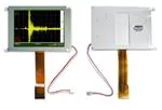


 工商网监
湘ICP备2023018690号
工商网监
湘ICP备2023018690号
