RF Chip Inductors
Wire Wound - 0805 Series
For More Information Please Visit: Networking.PulseElectronics.com
�WIRE WOUND RF CHIP INDUCTORS
0805CD SERIES
Wire wound ceramic core construction
High Q values
High self resonant frequency
Temperature Range -40 oC to +125 oC
Industry 0805 (2012) size and surface
mount land pattern
100% Tin Solder Termination
Electrical Specifications @ 25°C - Operating Temperature Range -40 oC to +125oC
Part Number
Tolerance +/-2%
Part Number
Tolerance +/-5%
Inductance 1
(nH)
Q2
(MIN)
SRF 3
(MHz MIN)
RDC 4
(Ω MAX)
IDC 5
(mA MAX)
PE-0805CD030GTT
PE-0805CD030JTT
3.32 @ 250MHz
40 @ 1500MHz
6000
0.08
600
PE-0805CD050GTT
PE-0805CD050JTT
5.6 @ 250MHz
50 @ 1500MHz
5500
0.10
600
PE-0805CD080GTT
PE-0805CD080JTT
7.9 @ 250MHz
50 @ 1000MHz
4700
0.12
600
PE-0805CD100GTT
PE-0805CD100JTT
10.2 @ 250MHz
50 @ 500MHz
4100
0.14
600
PE-0805CD120GTT
PE-0805CD120JTT
11.9 @ 250MHz
50 @ 500MHz
4000
0.15
600
PE-0805CD150GTT
PE-0805CD150JTT
14.9 @ 250MHz
50 @ 500MHz
3400
0.17
600
PE-0805CD180GTT
PE-0805CD180JTT
17.95 @ 250MHz
50 @ 500MHz
3300
0.20
600
PE-0805CD220GTT
PE-0805CD220JTT
21.7 @ 250MHz
55 @ 500MHz
2600
0.22
500
PE-0805CD270GTT
PE-0805CD270JTT
26.5 @ 250MHz
55 @ 500MHz
2500
0.25
500
PE-0805CD330GTT
PE-0805CD330JTT
32.75 @ 250MHz
60 @ 500MHz
2050
0.27
500
PE-0805CD390GTT
PE-0805CD390JTT
38.5 @ 250MHz
60 @ 500MHz
2000
0.29
500
PE-0805CD470GTT
PE-0805CD470JTT
46.6 @ 200MHz
60 @ 500MHz
1650
0.31
500
PE-0805CD560GTT
PE-0805CD560JTT
55.5 @ 200MHz
60 @ 500MHz
1550
0.34
500
PE-0805CD680GTT
PE-0805CD680JTT
67.8 @ 200MHz
60 @ 500MHz
1450
0.38
500
PE-0805CD820GTT
PE-0805CD820JTT
82.7 @ 150MHz
60 @ 500MHz
1300
0.42
400
PE-0805CD101GTT
PE-0805CD101JTT
98.7 @ 150MHz
60 @ 500MHz
1200
400
PE-0805CD111GTT
PE-0805CD111JTT
110 @ 150MHz
50 @ 250MHz
1000
0.46
0.48
PE-0805CD121GTT
PE-0805CD121JTT
119.7 @ 150MHz
50 @ 250MHz
1100
0.51
400
PE-0805CD151GTT
PE-0805CD151JTT
149.4 @ 100MHz
50 @ 250MHz
920
0.56
400
PE-0805CD181GTT
PE-0805CD181JTT
179.6 @ 100MHz
50 @ 250MHz
870
0.64
400
PE-0805CD221GTT
PE-0805CD221JTT
217 @ 100MHz
45 @ 250MHz
850
0.70
400
PE-0805CD271GTT
PE-0805CD331GTT
PE-0805CD391GTT
PE-0805CD271JTT
269 @ 100MHz
45 @ 250MHz
650
1.00
350
PE-0805CD331JTT
PE-0805CD391JTT
331 @ 100MHz
386 @ 50MHz
45 @ 250MHz
35 @ 250MHz
600
560
1.40
310
1.50
290
400
Pulse Jack
(Continued on next page)
www.networking.pulseelectronics.com
WC710.C (7/19)
Electronics
�WIRE WOUND RF CHIP INDUCTORS
0805CD SERIES
Electrical Specifications @ 25°C - Operating Temperature Range -40oC to +125oC
(continued)
Part Number
Tolerance +/-2%
Part Number
Tolerance +/-5%
Inductance 1
(nH)
Q2
(MIN)
SRF 3
(MHz MIN)
RDC 4
(Ω MAX)
IDC 5
(mA MAX)
PE-0805CD471GTT
PE-0805CD471JTT
477 @ 25MHz
33 @ 100MHz
375
1.76
250
PE-0805CD561GTT
PE-0805CD561JTT
545 @ 25MHz
23 @ 50MHz
340
1.90
230
PE-0805CD681GTT
PE-0805CD681JTT
674 @ 25MHz
23 @ 50MHz
188
2.20
190
PE-0805CD821GTT
PE-0805CD821JTT
783 @ 25MHz
23 @ 50MHz
215
2.35
180
PE-0805CD102GTT
PE-0805CD102JTT
1000 @25MHz
20 @ 50MHz
200
3.60
150
PE-0805CD122GTT
PE-0805CD122JTT
1200 @ 25MHz
20 @ 50MHz
200
4.10
120
N/A
PE-0805CD152JTT
1500 @ 25MHz
20 @ 50MHz
200
5.00
100
Notes:
1. Inductance measured using a HP4286A RF Impedance Analyzer. (Please note that inductance information
is not stamped on part, because of the extremely small size).
2. Q measured using a HP4291A RF Impedance Analyzer with a HP16193A Test Fixture.
3. SRF measured using a HP8753C Network Analyzer.
4. RDC measured using a Valhalla Scientific model 4100 ATC Digital Ohmeter.
5. Based on a 15�C maximum temperature rise.
6. Check ordered tolerance band carefully:
To order a +/-2% tolerance band the ordering code ends with "GTT"
while any+/-5% tolerance band ends with "JTT" .
Typical Q vs Frequency
Typical Inductance vs Frequency
Mechanical
Pulse Jack
3
Electronics
Weight ..................0.012grams
www.networking.pulseelectronics.com
Dimensions:
Inches
mm
WC710.C (7/19)
Unless otherwise specified,
all tolerances are ± .010
0,25
�WIRE WOUND RF CHIP INDUCTORS
0805FT SERIES
Wire wound ferrite core construction
High Q values
High self resonant frequency
Temperature Range -40 oC to +125 oC
Industry standard 0805 (2012) size and
surface mount land pattern
100% Tin Solder Termination
Electrical Specifications @ 25°C - Operating Temperature Range -40oC to +125oC
Part Number
Tolerance +/-5%
Notes:
Inductance
(uH)
1
2
3
4
5
Q
(MIN)
SRF
(MHz MIN)
RDC
(Ω MAX)
IDC
(mA MAX)
PE-0805FT102JTT
1.0 @ 7.96MHz
15 @ 7.96MHz
63
1.20
245
PE-0805FT152JTT
1.5 @ 7.96MHz
15 @ 7.96MHz
60
1.45
225
PE-0805FT222JTT
2.2 @ 7.96MHz
15 @ 7.96MHz
58
1.80
200
PE-0805FT332JTT
3.3 @ 7.96MHz
15 @ 7.96MHz
50
2.30
175
PE-0805FT472JTT
4.7 @ 7.96MHz
15 @ 7.96MHz
43
2.80
140
PE-0805FT682JTT
6.8 @ 7.96MHz
15 @ 7.96MHz
36
3.40
115
PE-0805FT103JTT
10 @ 2.52MHz
10 @ 2.52MHz
30
4.70
98
PE-0805FT153JTT
15 @ 2.52MHz
10 @ 2.52MHz
23
6.50
80
PE-0805FT223JTT
22 @ 2.52MHz
10 @ 2.52MHz
20
8.00
68
PE-0805FT333JTT
33 @ 2.52MHz
10 @ 2.52MHz
17
10.70
60
PE-0805FT473JTT
47 @ 2.52MHz
10 @ 2.52MHz
14
13.80
55
PE-0805FT683JTT
68 @ 2.52MHz
8 @ 2.52MHz
11
17.50
49
1. Inductance measured using a HP4286A RF Impedance Analyzer. (Please note that inductance information
is not stamped on part, because of the extremely small size).
2. Q measured using a HP4291A RF Impedance Analyzer with a HP16193A Test Fixture.
3. SRF measured using a HP8753C Network Analyzer.
4. RDC measured using a Valhalla Scientific model 4100 ATC Digital Ohmeter.
5. Based on a 15�C maximum temperature rise.
Mechanical
Dimensions:
Pulse Jack
4
Electronics
www.networking.pulseelectronics.com
Unless otherwise specified,
all tolerances are ± .010
0,25
Weight ..................0.012grams
Inches
mm
WC710.C (7/19)
�WIRE WOUND RF CHIP INDUCTORS
0805FT SERIES
Typical Q vs Frequency
Typical Inductance vs Frequency
Tape and Reel Specifications
Series
0805CD
0805FT
Packing Moisture Level = MSL 1 - Storage Temperature - 40oC to +125oC
Tape Dimensions (mm)
Reels Dimensions (mm)
Parts per
Reel
A
B
C
D
E
W
P1
P2
P3
H
T
2000
178
50
13
14.4
8.4
8
2
4
4
2.1
0.3
Notes: P1, P2 and P3 are same for all chip inductor series. Keeping the same dimensions for guide hole and pocket pitch (P1), pocket pitch (P2), guide hold pitch (P3) and tape width (8mm) for all series, enables the
packaging machine to maintain the same settings while changing models. The only difference between the series are the parts per reel which contributes to a different length of tapes/reel per model.
Pulse Jack
5
www.networking.pulseelectronics.com
WC710.C (7/19)
Electronics
�WIRE WOUND RF CHIP INDUCTORS
Performance testing
Electrical Testing
Storage and Operating
Temperature Range:
-40oC to +125oC
Thermal:
-40oC to +85oC
Moisture Resistance 240
Hours at 70oC
Operating Life
Inductors are subjected to the extremes for 48 hours.
Then tested at 25 oC
There shall be no deformation or change in appearance
Inductance shall not change by more than ±5%
Q values shall not change by more than ±10%
Inductors are subjected to 30 cycles for 30 minutes at
each extreme.
Then tested at 25 oC
Inductors are subjected to 10 cycles of 24 hours at 90
to 95% relative humidity
Then tested at 24 oC
Inductors are subjected to 1000 hours at
85 oC with 85% Relative Humidity with the rated
current applied
There shall be no Damaged, Open
or Shorted Windings
Mechanical Testing
Temperature Range:
Inductors are subjected to the following:
Use a solder pot at 260 oC, with RMA Flux. Each termination
is immersed in 63Sn/37Pb molten solder for 4 to 6 seconds.
There shall be no deformation or change in appearance
Inductance shall not change by more than ±5%
Q values shall not change by more than ±10%
Recommended Solder Heat
Resistance Profile
Physical Specifications
Vibration (Random)
Samplers are subjected to random
vibrations as per NAVMAT P9492
Mechanical Shock
Inductors are subjected to one half sine wave
pulse (8700 g's for 0.3ms) in each directional axis
for a total of 18 shocks
Moisture Resistance
Reflow Inductors on to test pads using 63Sn/37 Pb
solder paste
(IR Reflow profile = 200 oC for 30 seconds or peak
235 oC for 20 seconds)
6
www.networking.pulseelectronics.com
There shall be no deformation or change in appearance
Inductance shall not change by more than ±5%
Q values shall not change by more than ±10%
The inductors shall withstand a minimum force
of 1000 g's in any direction using a
dynamometer force guage
Pulse Jack
WC710.C (7/19)
Electronics
�
很抱歉,暂时无法提供与“PE-0805CD470JTT”相匹配的价格&库存,您可以联系我们找货
免费人工找货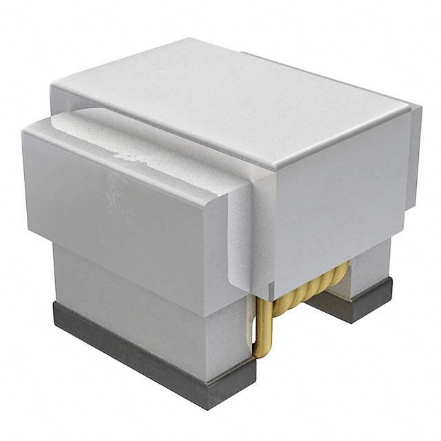


 工商网监
湘ICP备2023018690号
工商网监
湘ICP备2023018690号
