DATASHEET
ICS525-03
PECL INPUT OSCAR™ USER CONFIGURABLE CLOCK
Description
Features
The ICS525-03 are the most flexible way to generate a
high-quality, high-accuracy, high-frequency clock
output from a PECL input. The name OSCaR stands
for OSCillator Replacement, as they are designed to
replace crystal oscillators in almost any electronic
system. The user can configure the device to produce
nearly any output frequency from any input frequency
by grounding or floating the select pins. Neither
microcontroller, software, nor device programmer are
needed to set the frequency. Using Phase-Locked
Loop (PLL) techniques, the device accepts a PECL
clock to produce output clocks up to 250 MHz, keeping
them frequency locked together. Resistors are for
PECL outputs only.
• Packaged as 28-pin SSOP (150 mil body)
• Highly accurate frequency generation
• User determines the output frequency by setting all
•
•
•
•
•
•
•
•
•
•
•
•
For simple multipliers to produce common frequencies,
refer to the LOCOTM family of parts, which are smaller
and more cost effective.
This product is intended for clock generation. It has low
output jitter (variation in the output period), but input to
output skew and jitter are not defined nor guaranteed.
internal dividers
Eliminates need for custom oscillators
No software needed
Pull-ups on all select inputs
PECL input clock frequency of 0.5 to 250 MHz
Output clock frequencies up to 250 MHz
Very low jitter
Operating voltage of 3.0 V or 5.5 V
25 mA drive capability at TTL levels
Ideal for oscillator replacement
Industrial temperature
Available in Pb (lead) free package
Advanced, low-power CMOS process
NOTE: EOL for non-green parts to occur on
5/13/10 per PDN U-09-01
Block Diagram
2
VDD
VDD
62 Ohm
CLK1
PECLIN
PECLIN
Phase Comparator,
Charge Pump, and
Loop Filter
Reference
Divider
VCO
270 Ohm
Output
Divider
VDD
VCO
Divider
62 Ohm
CLK2
7
R6:R0
2
GND
9
V8:V0
IDT™ / ICS™ PECL INPUT OSCAR™ USER CONFIGURABLE CLOCK
3
S2:S0
1
270 Ohm
RES
ICS525-03
REV J 092209
�ICS525-03
PECL INPUT OSCAR™ USER CONFIGURABLE CLOCK
PECL MULTIPLIER
Pin Assignment
RES Value Table
28
R4
RES
CLK1
CLK2
Pre-divide (P)
2
27
R3
0
CMOS
CMOS
2
3
26
R2
S1
4
25
R1
1.1 kΩ Resistor
to VDD
PECL
PECL
1
R5
1
R6
S0
S2
5
24
R0
VDD
6
23
VDD
PECL
7
22
CLK2
PECLIN
8
21
CLK1
GND
9
20
GND
V0
10
19
RES
V1
11
18
V8
V2
12
17
V7
V3
13
16
V6
V4
14
15
V5
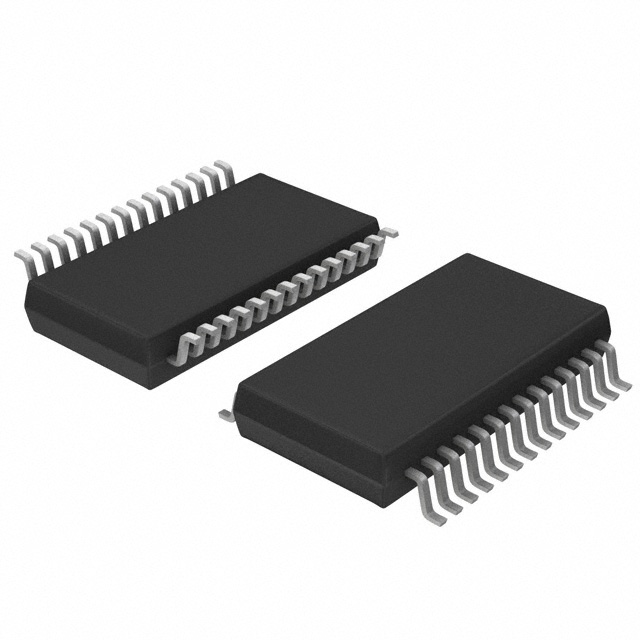
28-pin SSOP
Output Divider and Maximum Output Frequency Table
S0
S1
S2
CLK
pin 5
pin 4
pin 3
Output Divider
(OD)
Max. Output Frequency (MHz)
VDD = 5 V
VDD = 3.3 V
RES = 0
RES = 1.1 kΩ
RES = 0
RES = 1.1 kΩ
0
0
0
6
67
34
40
20
0
0
1
2
200
100
120
60
0
1
0
8
50
25
30
15
0
1
1
4
100
50
60
30
1
0
0
5
80
40
48
24
1
0
1
7
57
29
34
17
1
1
0
1
250
200
200
125
1
1
1
3
133
80
80
40
Note: 0 = connect directly to ground; 1 = connect directly to VDD.
IDT™ / ICS™ PECL INPUT OSCAR™ USER CONFIGURABLE CLOCK
2
ICS525-03
REV J 092209
�ICS525-03
PECL INPUT OSCAR™ USER CONFIGURABLE CLOCK
PECL MULTIPLIER
Pin Descriptions
Pin
Number
Pin
Name
Pin
Type
Pin Description
1, 2,
24-28
R5, R6,
R0-R4
I(PU)
Reference divider word input pins determined by user. Forms a binary
number from 0 to 127.
3, 4, 5
S0, S1, S2
I(PU)
Select pins for output divider determined by user. See table above.
6, 23
VDD
Power
Connect to VDD.
7
PECLIN
Input
PECL input.
8
PECLIN
Input
Complementary PECL input.
9, 20
GND
Power
Connect to ground.
10 - 18
V0 - V8
I(PU)
VCO divider word input pins determined by user. Forms a binary number from
0 to 511.
19
RES
Input
Select eithe PECL or CMOS outputs. See table above.
21
CLK1
Output
Output clock. Either PECL or CMOS determined by RES.
22
CLK2
Output
Output clock. Either PECL or CMOS determined by RES.
KEY: I(PU) = Input with internal pull-up resistor.
Output Clock Selection
If RES is connected directly to ground, CLK1 and CLK2 are low skew, CMOS outputs clocks. They are not
complementary. If RES is connected to VDD through a 1.1 kΩ resistor, then CLK1 and CLK2 become
complementary PECL outputs which require the external resistor network shown in the the block diagram. Refer to
Application Note MAN09 for additional information.
IDT™ / ICS™ PECL INPUT OSCAR™ USER CONFIGURABLE CLOCK
3
ICS525-03
REV J 092209
�ICS525-03
PECL INPUT OSCAR™ USER CONFIGURABLE CLOCK
PECL MULTIPLIER
External Components/Crystal
Selection
Pre-divide (P) = values on page 2 under RES Value
Table
Decoupling Capacitors
Also, the following operating ranges should be
observed:
The ICS525-03 requries two 0.01µF decoupling
capacitors to be connected between VDD and GND,
one on each side of the chip. The capacitor must be
connected close to the device to minimize lead
inductance. No external power supply filtering is
required for this device.
10 MHz < Input frequency x
(VDW+8)
很抱歉,暂时无法提供与“ICS525R-03I”相匹配的价格&库存,您可以联系我们找货
免费人工找货