Datasheet
LED Drivers for Automotive Light
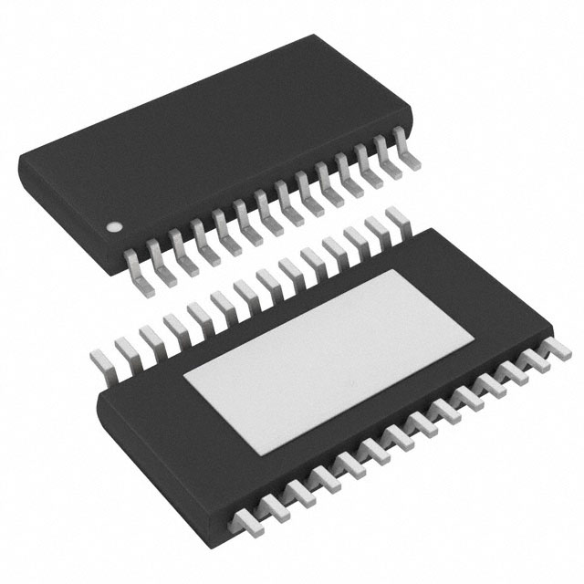
BD8381AEFV-M
General Description
Key Specifications
Input Supply Voltage Range:
Operating Temperature Range:
BD8381AEFV-M is a white LED driver with the
capability of withstanding high input voltage (50V MAX).
It has also an integrated current-mode, buck-boost
DC/DC controller to achieve stable operation against
high input voltage and to remove the constraint of the
number of LEDs in series connection.
The LED brightness is controlled by either linear or
PWM signal and is also possible to be controlled even
without using a microcomputer, but instead, by means
of the built-in PWM brightness signal generation circuit.
Package
5.0V to 30V
-40°C to +125°C
W(Typ) x D(Typ) x H(Max)
Features
Integrated buck-boost current-mode DC/DC
controller
Built-in CR timer for PWM brightness
PWM linear brightness
Built-in protection functions (UVLO, OVP, TSD, OCP,
SCP)
LED error status detection function (OPEN/
SHORT)
HTSSOP-B28
9.70mm x 6.40mm x 1.00mm
Applications
Headlight and Daytime Running Light etc.
Typical Application Circuit and Block Diagram
VREG
Vin
FAIL1
OVP
UVLO
VCC
TSD
COUT
OVP
OCP
CS
VREG
Timer
Latch
EN
PWM
BOOT
Control Logic
OUTH
DRV
CTL
SYNC
OSC
SLOPE
SW
PWM
DGND
RT
VREG
OUTL
ERR AMP
GND
-
COMP
+
SS
VREG
LEDR
+
OCP OVP
SHORT
Det
LEDC
SS
PWMOUT
THM
INP1
FB
INP2
DRLIN
VREG
OPEN/ SHORT/ SCP Detect
DISC
CR
TIMER
Open Det
VTH
Timer
Latch
FAIL2
CT
PGND
〇Product structure: Silicon monolithic integrated circuit
.www.rohm.com
© 2014 ROHM Co., Ltd. All rights reserved.
TSZ22111 • 14 • 001
SCP Det
〇This product has no designed protection against radioactive rays
1/36
TSZ02201-0T1T0C700160-1-2
31.Oct.2014 Rev.001
�BD8381AEFV-M
Pin Configuration
(TOP VIEW)
1
28
2
27
3
26
4
25
5
24
6
23
7
22
8
21
9
20
10
19
11
18
12
17
13
16
14
15
Pin Descriptions
Pin
1
2
3
4
5
6
7
8
9
10
11
12
13
14
15
16
17
18
19
20
21
22
23
24
25
26
27
28
Symbol
COMP
SS
VCC
EN
RT
SYNC
GND
THM
FB
DISC
VTH
DRLIN
FAIL1
FAIL2
OVP
LEDC
LEDR
N.C.
PGND
PWMOUT
CT
OUTL
DGND
SW
OUTH
CS
BOOT
VREG
www.rohm.com
© 2014 ROHM Co., Ltd. All rights reserved.
TSZ22111・15・001
Function
Error amplifier output
Soft start setting input
Input power supply
Enable input
Oscillation frequency-setting resistance input
External synchronization signal input
Small-signal GND
Thermally sensitive resistor connection pin
ERRAMP FB signal input pin
CR Timer discharge pin
CR Timer threshold pin
DRL switch pin (Pulse output setting pin)
Failure signal output
LED open/short detection signal output
Over-voltage detection input
LED short detection pin (LED detection side)
LED short detection pin (Resistor detection side)
PWM brightness source pin
PWM brightness signal output pin
GND short protection timer setting pin
Low-side external FET Gate Drive out put
Low-side FET driver source pin
High-side FET Source pin
High-side external FET Gate Drive out put
DC/DC output current detection pin
High-side FET driver source pin
Internal reference voltage output
2/36
TSZ02201-0T1T0C700160-1-2
31.Oct.2014 Rev.001
�BD8381AEFV-M
Absolute Maximum Ratings (Ta=25°C)
Parameter
Symbol
Rating
Unit
VCC
50
V
VBOOT
55
V
VSW, VCS, VOUTH
50
V
VBOOT-SW
7
V
-0.3 to +7 < VCC
V
Power Supply Voltage
Boot Voltage
SW,CS,OUTH Voltage
BOOT-SW Voltage
VREG,OVP,OUTL,FAIL1,FAIL2,THM,SS,
COMP,RT,SYNC,EN,DISC,VTH,FB,LEDR,
LEDC,DRLIN, PWMOUT,CT Voltage
VREG, VOVP, VOUTL, VFAIL1,
VFAIL2, VTHM, VSS,
VCOMP, VRT, VSYNC, VEN,
VDISC, VVTH, VFB, VLEDR,
VLEDC, VDRLIN, VPWMOUT, VCT
Power Consumption
Pd
1.45
(Note 1)
W
Operating Temperature Range
Topr
-40 to +125
°C
Storage Temperature Range
Tstg
-55 to +150
°C
Tjmax
150
°C
Junction Temperature
(Note 1) IC mounted on glass epoxy board measuring 70mm x 70mm x 1.6mm, power dissipated at a rate of 11.60mW/°C at temperatures above 25°C.
Caution: Operating the IC over the absolute maximum ratings may damage the IC. The damage can either be a short circuit between pins or an open circuit
between pins and the internal circuitry. Therefore, it is important to consider circuit protection measures, such as adding a fuse, in case the IC is operated
over the absolute maximum ratings..
Recommended Operating Conditions (Ta=25°C)
Parameter
Symbol
Rating
Unit
Power Supply Voltage
VCC
5.0 to 30
V
Oscillating Frequency Range
fOSC
100 to 600
kHz
fSYNC
fOSC to 600
kHz
fSDUTY
40 to 60
%
External Synchronization Frequency Range
(Note 2) (Note 3)
External Synchronization Pulse Duty Range
(Note 2) Connect SYNC to GND or OPEN when not using external frequency synchronization.
(Note 3) Do not switch between internal and external synchronization when an external synchronization signal is input to the device.
www.rohm.com
© 2014 ROHM Co., Ltd. All rights reserved.
TSZ22111・15・001
3/36
TSZ02201-0T1T0C700160-1-2
31.Oct.2014 Rev.001
�BD8381AEFV-M
Electrical Characteristics (Unless otherwise specified, VCC=12V Ta=25°C)
Parameter
Circuit Current
Standby Current
[VREG Block (VREG)]
Reference Voltage
[OUTH Block]
OUTH High-Side ON-Resistance
OUTH Low-Side ON-Resistance
Over-Current Protection
Operating Voltage
SS Charge Current
[OUTL Block]
OUTL High-Side ON-Resistance
OUTL Low –Side ON-Resistance
[SW Block]
SW Low -Side ON-Resistance
[PWMOUT Block]
PWMOUT High-Side ON-Resistance
PWMOUT Low-Side ON-Resistance
[Error Amplifier Block]
Reference Voltage1
Reference Voltage2
The Amount of Change of VREF
by Temperature
COMP Sink Current
COMP Source Current
Max Duty Output
[Oscillator Block]
Oscillating Frequency
[OVP Block]
Over-Voltage Detection
Reference Voltage
OVP Hysteresis Width
[UVLO Block ]
UVLO Voltage
UVLO Hysteresis Width
[PWM Generation Circuit Block]
VTH Threshold Voltage
VTH Threshold Voltage
PWM Minimum ON Width
LED OPEN Detection Function
LED SHORT Detection Function
LED GND Short Protection Timer
[Logic Inputs]
Input HIGH Voltage
Input LOW Voltage
Input Current 1
Input Current 2
[FAIL Output (Open Drain) ]
Fail LOW Voltage
www.rohm.com
© 2014 ROHM Co., Ltd. All rights reserved.
TSZ22111・15・001
Min
Limit
Typ
Max
ICC
-
4.5
7.0
mA
ISTBY
-
0
8
µA
EN=Hi, SYNC=Hi,
RT=OPEN, CIN=10µF
EN=Low
VREG
4.5
5.0
5.5
V
IREG=-5mA, CREG=10µF
RONHH
RONHL
3.5
2.5
VCC
-0.60
5
7.0
5.0
VCC
-0.52
7
Ω
Ω
ION=-10mA
ION=10mA
ISS
1.5
1.0
VCC
-0.68
3
µA
VSS=0V
RONLH
RONLL
2.0
1.0
4.0
2.5
8.0
5.0
Ω
Ω
ION=-10mA
ION=10mA
RONSW
2.0
4.5
9.0
Ω
IONSW=10mA
RONPWMH
RONPWML
2.0
1.0
4.0
2.5
8.0
5.0
Ω
Ω
IONPWMH=-10mA
IONPWML=10mA
VREF1
VREF2
0.194
0.190
0.200
0.200
0.206
0.210
V
V
FB-COMP Short,1MΩ/250kΩ
dVREF2
-0.090
-0.045
-0.003
mV/°C
ICOMPSINK
ICOMPSOURCE
Dmax
50
-100
83
75
-75
90
100
-50
-
µA
µA
%
fOSC
285
300
315
KHz
VOVP
1.9
2.0
2.1
V
VOVP=Sweep up
VOHYS
0.45
0.55
0.65
V
VOVP= Sweep down
VUVLO
VUHYS
4.0
50
4.35
150
4.7
250
V
mV
VCC= Sweep down
VCC= Sweep up
VTH1
VTH2
tPWMON
VOPEN
VSHORT
tSHORT
3
1
25
30
100
100
2/3VREG
1/3VREG
50
200
150
3.7
2
70
400
200
V
V
µs
mV
mV
ms
VSHORT ≥ lVLEDR-VLEDCl
CCT=0.1µF
VINH
VINL
IIN
IEN
3.0
GND
20
15
35
30
1.0
50
45
V
V
µA
µA
VIN=5V (SYNC/DRLIN)
VEN=5V (EN)
VOL
-
0.1
0.2
V
IOL=0.1mA
Symbol
VOLIMIT
4/36
Unit
Conditions
V
FB-COMP Short,1MΩ/250kΩ
Ta=-40°C to +125°C
VFB=0.4V, VCOMP=1V
VFB=0V, VCOMP=1V
fOSC=300kHz
RRT=200kΩ
TSZ02201-0T1T0C700160-1-2
31.Oct.2014 Rev.001
�BD8381AEFV-M
Typical Performance Curves
(Unless otherwise specified, Ta=25°C)
6
700
VCC=12V
Oscillating Frequency: fOSC [kHz]
Output Voltage: VREG [V]
600
4
2
500
RRT=100kohm
400
300
200
RRT=200kohm
100
0
0
0
5
10
15
20
25
30
35
40
45
-50
50
-25
0
25
50
75
100
125
TEMPERATURE:
[℃]
Temperature: TaTa[°C]
VCC Voltage:
Power Supply
Voltage: [V]
VCC [V]
Figure 2. Oscillating Frequency vs Temperature
(fOSC Temperature Characteristic)
Figure 1. Output Voltage vs Power Supply Voltage
(VREG Voltage Characteristic)
0.22
8.0
VCC=12V
0.21
Circuit Current: ICC [mA]
Output Voltage: VCC-VCS [V]
0.215
0.205
0.2
0.195
0.19
6.0
4.0
2.0
0.185
0.18
-50
0.0
-25
0
25
50
75
100
0
125
10
15
20
25
30
35
40
45
50
[V]
PowerSupply
SupplyVoltage:
Voltage:VV
[V]
CCCC
Temperature: Ta [°C]
Figure 4. Circuit Current vs Power Supply Voltage
Figure 3. Output Voltage vs Temperature
(Standard Voltage Temperature Characteristic)
www.rohm.com
© 2014 ROHM Co., Ltd. All rights reserved.
TSZ22111・15・001
5
5/36
TSZ02201-0T1T0C700160-1-2
31.Oct.2014 Rev.001
�BD8381AEFV-M
Typical Performance Curves – continued
(Unless otherwise specified, Ta=25°C)
0.66
100
90
Buck
VOUT=6V
0.62
0.60
0.58
VVCC=12V
CC= 12V
Efficiency [%]
85
Efficiency [%]
Output Voltage: VCC-VCS [V]
0.64
ILED=0.6A
Boost
VOUT=24V
95
80
Buck-Boost
VOUT=14V
75
70
0.56
65
0.54
60
-50
-25
0
25
50
75
100
6
125
21
Figure 6. Efficiency vs Power Supply Voltage
(Input Voltage Dependence)
Figure 5. Output Voltage vs Temperature
(Overcurrent Detection Voltage Temperature
Characteristic)
10
250
VCC=12V
200
150
100
50
VCC=12V
PWMOUT
Output Voltage:
[V] [V]
PWMOUT
OUTPUT
VOLTAGE
Reference Voltage: VREF [mV]
12
15
18
SUPPLY VOLTAGE:Vcc [V]
Power Supply Voltage: VCC [V]
Temperature:
Temperature: Ta
Ta [°C]
[℃]
REFERENCEVOLTAGE :VREF [mV]
9
8
6
4
2
1/3VREG
2/3VREG
0
0
0
0 0.1 0.2 0.3 0.4 0.5 0.6 0.7 0.8 0.9 1 1.1
THMVoltage:
VOLTAGE:THM[V]
THM
THM [V]
5
VTH Voltage: VVTH [V]
Figure 8. PWMOUT Output Voltage vs
VTH Threshold Voltage
Figure 7. Reference
vs THM Voltage
Figure Voltage
7. THM Gain
(THM Gain)
www.rohm.com
© 2014 ROHM Co., Ltd. All rights reserved.
TSZ22111・15・001
1
2
3
4
VTH
VOLTAGE:VVTH
[V]
VTH Voltage: VVTH [V]
6/36
TSZ02201-0T1T0C700160-1-2
31.Oct.2014 Rev.001
�BD8381AEFV-M
Typical Performance Curves – continued
(Unless otherwise specified, Ta=25°C)
10
VCC=12V
VCC=12V
Ta=25°C
Ta=-40°C
Output Voltage: VREG [V]
8
OUTPUT VOLTAGE:VREG [V]
Output Voltage: VPWMOUT [V]
OUTPUT VOLTAGE:PWMOUT [V]
10
Ta=125°C
6
4
2
0
Ta=25°C
8
Ta=125°C
6
4
2
0
0
1
2
3
4
DRLIN
VOLTAGE:VDRLIN
DRLIN
Voltage: VDRLIN [V][V]
5
0
Over-Voltage Detection Reference Voltage: VOVP [V]
5.5
VCC=12V
5.4
Over voltage detection voltage: VOVP[V]
5.3
OUTPUT Voltage: VREG[V]
5.2
5.1
5
4.9
4.8
4.7
4.6
4.5
-50
-25
0
25
50
75
TEMPERATURE:Ta [℃]
100
125
2
3
4
ENEN
VOLTAGE:VEN
Voltage: VEN [V][V]
5
2.15
VCC=12V
2.1
2.05
2
1.95
1.9
1.85
-50
-25
0
25
50
75
TEMPERATURE:Ta [℃]
100
125
Temperature: Ta [°C]
Temperature: Ta [°C]
Figure 12. Over-Voltage Detection Reference Voltage vs
Temperature
(OVP Voltage Temperature Characteristic)
Figure 11. Output Voltage vs Temperature
(VREG Voltage Temperature Characteristic)
www.rohm.com
© 2014 ROHM Co., Ltd. All rights reserved.
TSZ22111・15・001
1
Figure 10. Output Voltage vs EN Threshold Voltage
(DRLIN=VREG)
Figure 9. Output Voltage vs DRLIN Threshold Voltage
Output Voltage: VREG [V]
Ta=-40°C
7/36
TSZ02201-0T1T0C700160-1-2
31.Oct.2014 Rev.001
�BD8381AEFV-M
Typical Performance Curves – continued
(Unless otherwise specified, Ta=25°C)
400
60
55
50
45
40
35
30
-50
-25
0
25
50
75
TEMPERATURE:Ta [℃]
100
250
200
150
-25
0
25
50
75
TEMPERATURE:Ta [℃]
100
125
Temperature: Ta [°C]
Temperature: Ta [°C]
Figure 13. LED Open Detection Voltage vs
Temperature
www.rohm.com
© 2014 ROHM Co., Ltd. All rights reserved.
TSZ22111・15・001
300
100
-50
125
VCC=12V
VLEDR=2V
350
LED short detection voltage: Vshort[mV]
LED Short Detection Voltage: VSHORT [mV]
VCC=12V
65
LED open detection voltage: Vopen[mV]
LED Open Detection Voltage: VOPEN [mV]
70
Figure 14. LED Short Detection Voltage vs
Temperature
8/36
TSZ02201-0T1T0C700160-1-2
31.Oct.2014 Rev.001
�BD8381AEFV-M
Application Information
1. Application Circuit
Application Circuit 1
VREG
Vin
FAIL1
OVP
UVLO
VCC
TSD
COUT
OVP
OCP
CS
VREG
Timer
Latch
EN
PWM
BOOT
Control Logic
OUTH
DRV
CTL
SYNC
SW
PWM
SLOPE
OSC
DGND
RT
VREG
OUTL
ERR AMP
GND
-
COMP
+
SS
LEDR
+
OCP OVP
SHORT
Det
LEDC
SS
VREG
PWMOUT
THM
INP1
FB
INP2
DRLIN
VREG
OPEN/ SHORT/ SCP Detect
CR
TIMER
DISC
Open Det
VTH
Timer
Latch
FAIL2
SCP Det
PGND
CT
Figure 15
Buck application composition (It is INP1, INP2 and two input selector function and EN connected direct to VCC)
Application Circuit 2
VREG
Vin
FAIL1
OVP
UVLO
VCC
TSD
COUT
OVP
OCP
CS
VREG
Timer
Latch
EN
PWM
BOOT
Control Logic
OUTH
DRV
CTL
SYNC
OSC
SLOPE
SW
PWM
DGND
RT
VREG
OUTL
ERR AMP
GND
-
COMP
SS
LEDR
+
OCP OVP
VREG
VREG
+
SHORT
Det
30kΩ
LEDC
20kΩ
SS
PWMOUT
THM
FB
DRLIN
VREG
OPEN/ SHORT/ SCP Detect
DISC
CR
TIMER
Open Det
VTH
Timer
Latch
SCP Det
FAIL2
CT
PGND
Figure 16
Boost application composition (When invalidating short detection and EN is inputted by a voltage divider)
www.rohm.com
© 2014 ROHM Co., Ltd. All rights reserved.
TSZ22111・15・001
9/36
TSZ02201-0T1T0C700160-1-2
31.Oct.2014 Rev.001
�BD8381AEFV-M
2. Reference PCB Setting
VCC
CVCC1
CVCC3
CVCC2
VREG
COMP
VREG
SS
BOOT
VREG
CREG
CCS
RCS2
RPC
RCS1
CPC
CSS
SYNC
DGND
GND
OUTL
ROUTL
ROVP1
RTHM21
THM1
VOUT
COUT1
SYNC
DI2
RSW1
DGND
RLEDR1
SW
TR
RLEDR2
RT
CBOOT
COUT2
RRT
OUTH
RSW2
RTHM3
RTHM11
GND
CS
EN
RQ1
SW1
EN
ROVP2
VCC
VREG
VREG
RCS3
LEDOUT
CCT
THM
FB
CCR
VTH
VTH
SW2
RFL1
PGND
PGND
N.C.
DRLIN
LEDR
FAIL1
LEDC
FAIL2
OVP
RSENSE2
THM2
RCR2
RSENSE1
RCR1
PWMOUT
DISC
RQ3
CT
LEDR
LEDC
VREG
RFL2
FAIL1
FAIL2
Figure 17
VCC=8V to 16V, VOUT=16V, ILED=1A, fOSC=300kHz, PWM dummign25%, PWM Frequency 130Hz
No.
Component
Name
Component Value
Component
Product Name
No.
23
CCS
N.M
-
24
CBOOT
0.1μF
GCM188R11H104KA42
Name
Component Value
Product Name
1
CVCC1
10μF
2
CVCC2
10μF
GCM32ER71E106KA42
GCM32ER71E106KA42
3
CVCC3
0.1μF
GRM31CB31E104KA75B
25
Q1
RSS070N05
-
4
CPC
0.1μF
GCM188R11H104KA42
26
DI1
RB050L-40
-
5
RPC
MCR03 Series
27
RSW1
6
CSS
GCM188R11H104KA42
28
RSW2
N.M
7
RRT
200kΩ
MCR03 Series
29
RQ1
N.M
-
8
RTHM11
100kΩ
MCR03 Series
30
L
10μH
SLF12575T100M5R4-H
820Ω
0.1μF
0Ω
-
9
RTHM12
100kΩ
MCR03 Series
31
ROUTL
10
RTHM21
100kΩ
MCR03 Series
32
Q2
RSS070N05
11
RTHM22
100kΩ
MCR03 Series
33
DI2
RF201L2S
-
12
RTHM3
0Ω
-
34
COUT1
10μF
GCM32ER71E106KA42
-
0Ω
-
MCR03
Series -
13
TR
35
COUT2
10μF
GCM32ER71E106KA42
14
RCR1
30kΩ
MCR03 Series
36
CCT
0.1μF
GCM188R11H104KA42
15
RCR2
10kΩ
MCR03 Series
37
ROVP1
270kΩ
16
CCR
GCM21BR11H224KA01
38
ROVP2
30kΩ
17
FRL1
100kΩ
MCR03 Series
39
RLEDR1
90kΩ
18
FRL2
100kΩ
MCR03 Series
39
RLEDR2
30kΩ
19
CREG
10μF
GCM32ER71E106KA42
40
Q3
20
RCS1
110mΩ
MCR100JZHFSR110
41
RQ3
RSS070N0
5 N.M
21
RCS2
N.M
-
42
RSENSE1
200mΩ
22
RCS3
-
43
RSENSE2
N.M
0.22μF
0Ω
MCR03
Series
MCR03
Series
MCR03
Series
MCR03
Series MCR100JZHFSR510
-
(Note)
When no PWM dimming, DI2 should be a schottky diode instead of a Fast Recovery diode to improve efficiency.
When dimming with External PWM signal, DISC should be pulled up to VREG with 10KΩ,then input PWM signal to
VTH.(when no PWM dimming, remove Q3 and replace RQ3=0Ω and short to DS)
Efficiency improvement is possible by making DI2 a schottky Diode .However, since high temperature leakage current is
large and output voltage ripple is large as well, LED may flicker when PWM dimming ratio is very low. So it is
recommended to use a Fast recovery Diode.
Values of the capacitors can be smaller than the amount that was selected by the DC bias characteristics of the capacitor
when using ceramic capacitors.
For EMI reduction, please insert resistance to ROUTL and RBOOT. It is recommended to be below 20Ω.
The output voltage ripple is larger in Boost application than in Buck application. Hence, it is recommended to use at least
100µ F output capacitor.
www.rohm.com
© 2014 ROHM Co., Ltd. All rights reserved.
TSZ22111・15・001
10/36
TSZ02201-0T1T0C700160-1-2
31.Oct.2014 Rev.001
�BD8381AEFV-M
3. 5V Voltage Reference (VREG)
5V (Typ) is generated from the VCC input voltage when the enable pin is set high. This voltage is used to power internal
circuitry, as well as the voltage source for device pins that need to be fixed to a logical HIGH.
UVLO protection is integrated into the VREG pin. The voltage regulation circuitry operates uninterrupted for output
voltages higher than 4.5 V (Typ), but if output voltage drops to 4.3 V (Typ) or lower, UVLO engages and turns the IC off.
Connect a capacitor (CREG = 10µF Typ) to the VREG terminal for phase compensation. Operation may become unstable if
CREG is not connected.
4. LED Current Setting and Control Method.
(1) Method of setting the LED current
The LED current can be calculated by the following formula.
THM ≥1.0V→ILED=0.2V(Typ) / RSET
THM


 工商网监
湘ICP备2023018690号
工商网监
湘ICP备2023018690号

