Ordering number: ENA2095
LB11970RV
Monolithic Digital IC
For Fan Motor
Single-phase Full-wave Driver
http://onsemi.com
Overview
The LB11970RV is a motor driver of the single phase bipolar drive that a good direct PWM drive of the motor drive
efficiency can come true easily. It is most suitable for the power supply fan of the personal computer, CPU air
conditioner fan drive.
Functions
• Single-phase full-wave drive (16V to 1.2A output transistor incorporated)
• Variable speed function using thermistor input and external signal incorporated
→Enables silent and low-vibration variable speed control through direct PWM control with separately-excited upper
Tr
• Current limiter circuit (limit at IO=480mA with RL=1Ω connection, the limiter value determined with Rf)
• Kick-back absorption circuit incorporated
• Low-consumption, low-loss, and low-noise drive enabled by the soft switching circuit during phase shift
• Regeneration Di incorporated with less external parts
• HB incorporated
• Lock protection and automatic reset functions incorporated
• RD (Lock detection) output
• Thermal shutdown circuit incorporated
Specifications
Absolute Maximum Ratings at Ta = 25°C
Parameter
Symbol
Conditions
Ratings
Unit
VCC maximum supply voltage
VCC max
17
V
VM maximum supply voltage
VM max
17
V
OUT pin maximum output current
IOUT max
1.2
A
OUT pin output withstand voltage
VOUT max
18
V
HB maximum output current
HB
10
mA
VTH, RMI input pin withstand voltage
VTH RMI max
7
V
VCC
V
P-IN input pin withstand voltage
VP-IN max
RD output pin output withstand voltage
VRD max
18
V
RD output current
IRD max
10
mA
Allowable power dissipation
Pd max
0.8
W
Operating temperature range
Topr
Specified substrate *
-30 to 90
°C
Storage temperature range
Tstg
-55 to 150
°C
* Specified substrate: 30mm×30mm×0.8mm, paper phenol.
Caution 1) Absolute maximum ratings represent the value which cannot be exceeded for any length of time.
Caution 2) Even when the device is used within the range of absolute maximum ratings, as a result of continuous usage under high temperature, high
current, high voltage, or drastic temperature change, the reliability of the IC may be degraded. Please contact us for the further details.
Stresses exceeding Maximum Ratings may damage the device. Maximum Ratings are stress ratings only. Functional operation above the Recommended Operating
Conditions is not implied. Extended exposure to stresses above the Recommended Operating Conditions may affect device reliability.
Semiconductor Components Industries, LLC, 2013
May, 2013
71812 SY 20060927-S00008 No.A2095-1/7
�LB11970RV
Recommended Operating Ranges at Ta = 25°C
Parameter
Symbol
Conditions
Ratings
Unit
VCC supply voltage
VCC
4.5 to 16
V
VM supply voltage
VM
3.5 to 16
V
VTH, RMI input level voltage range
VTH, RMI
0 to 6
V
0 to VCC
V
P-IN input level voltage range
VP-IN
Triangular wave input range
VRM
0.5 to 4
V
Hall input common phase input voltage range
VICM
0.2 to 3
V
Electrical Characteristics at Ta = 25°C, VCC = 12V, Rf = 0Ω, unless otherwise specified.
Parameter
Symbol
Ratings
Conditions
min
Circuit current
typ
unit
max
ICC1
During drive
12
15
18
mA
ICC2
During lock protection
11
14
17
mA
HB voltage
VHB
IHB=5mA
1.12
1.22
1.32
V
6VREG voltage
V6VREG
I6VREG=5mA
5.85
5.95
6.10
V
CT pin H level voltage
VCTH
3.4
3.6
3.8
V
CT pin L level voltage
VCTL
1.4
1.6
1.8
V
CT pin charge current
ICT1
1.8
2.2
2.6
μA
CT pin discharge current
ICT2
0.18
0.22
0.26
μA
CT charge/discharge current ratio
RCT
10
12
OUT output L saturation voltage
VOL
IO=200mA
0.1
0.2
V
OUT output H saturation voltage
VOH
IO=200mA, Rf=1Ω
0.6
0.8
V
Current limiter
VRF
RD output pin L voltage
VRD
IRD=5mA
RD output pin leak current
IRDL
VRD=18V
Overheat protection circuit
THD
* Design guarantee value
8
480
0.2
180
mV
0.3
V
30
μA
°C
*: Design target value and no measurement were made.
No.A2095-2/7
�LB11970RV
Package Dimensions
unit : mm (typ)
3338
Pd max - Ta
8.0
1.0
Allowable Power Dissipation, Pd max - W
0.5
4.4
10
6.4
18
1
9
0.8
0.3
0.15
0.1
(1.5)
1.7MAX
(0.8)
Mounted on a board: 30mm×30mm×0.8mm,
paper phenol
0.8
0.6
0.4
0.38
0.2
0
-30
-10
10
30
50
70
90
110
Ambient Temperature, Ta - °C
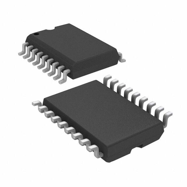
SANYO : SSOP18(225mil)
Pin Assignment
OUT2
1
18 P-GND
VM
2
17 OUT1
VCC
3
16 S-GND
WH
4
15
6VREG
WL
5
14
CT
VTH
6
13
IN-
RMI
7
12 HB
P-IN
8
11 IN+
CPWM
9
10
LB11970RV
RD
(Top view)
PGND: Motor system GND
SGND: Control system GND
No.A2095-3/7
�LB11970RV
Equivalent Circuit Diagram
RD
RMI
VTH
H: Rotation mode
CPWM
Thermal shat down
L: Regeneration mode
P-IN
VCC
Comparator
Current control
circuit
VM
Constant voltage
Delay circuit
6VREG
HALL
Controller
1.25V
HB
OUT
M
IN+
Delay circuit
IN-
OUT
Hysteresis
AMP
Charge/discharge
circuit
CT
SGND
Oscillation
P-IN RMI VTH
WH WL
CPWM
PGND
Truth Table
VTH
PIN
IN-
L
L
H
L
H
L
(OPEN)
L
L
H
L
H
L
H
L
OFF
L
L
L
H
L
OFF
-
H
H
L
-
H
L
H
-
-
H
L
-
-
L
H
H
VTH, P-IN = L means VTH, P-IN < CPWM
IN+
CT
L
OUT1
OUT2
RD
Mode
Running - drive
L
Running - regeneration
OFF
L
Output regeneration mode
L
OFF
with external signal
H
OFF
L
H
L
OFF
L
OFF
Lock protection
VTH, P-IN = H means VTH, P-IN > CPWM
No.A2095-4/7
�LB11970RV
Application Circuit Example
Rf
*4
CM
VCC
*2
VM
HB
*8
IN-
H
*5
*7
IN+
FG
6VREG
*3-3
R6
R4
PIN
*3-1
R5
C=2200 to 4700pF
R=20 to 50Ω
R1
WH
PWM-IN
R2
OUT1
R3
WL
R7
*3-2
RMI
RTU
OUT2
R8
R1
*3
WH
VTH
R2
PGND
TH
CPWM
CP=100pF
*f=25kHz
*1
WL
*6
R3
CT
CT=0.47 to 1μF
SGND
No.A2095-5/7
�LB11970RV
*1. Power supply - GND wiring
PGND is connected to the motor power system while SGND is connected to the control circuit power system.
Wiring is made separately for PGND and SGND, and external parts of each control system are connected to SGND.
*2. Power stabilization capacitor for regeneration
CM capacitor is a power stabilizing capacitor for PWM drive and kick-back absorption and has the capacitance of
4.7μF or more. Since this IC performs current regeneration with the lower Tr through switching of the upper Tr,
connect CM with the thick and shortest possible pattern between VM and PGND.
*3. Setting of the temperature detection variable speed
Setting of the triangular wave oscillation voltage
The rotation speed variable range for the temperature is set with the triangular wave oscillation voltage.
There are two setting methods as follows:
3-1
3-2
The upper voltage (VCPH) of triangular wave is determined by V[voltage of the R1 connection counterpart]×
(R2/(R1+R2)) and the lower voltage (VCPL) of triangular wave is determined by V× ((R2//R3) / (R1+R2//R3)).
The upper voltage (VCPH) of triangular wave is determined by V× ((R2+R3) / (R1+R2+R3)) and the lower voltage
(VCPL) of triangular wave is determined by V× (R2/(R1+R2)).
Setting of the thermostat
The resistance (RTU from VCC or 6VREG and the voltage generated through division of thermostat (TH) are input
in the VTH pin. When the voltage at the VTH pin drops below VCPL due to temperature change, the full speed
(thermostat input speed control side only) is obtained.
To set the full speed with the thermostat tripping, connect each pin of 3-3 to VCC and each input voltage is
generated by divided resistance from VCC. When the thermostat trips and the VTH pin is pulled up to VCC, the full
speed (thermostat input speed control side only) is obtained.
*4. Setting the current limiter
The current limiter is activated when the voltage between current detection resistors exceeds 0.48V between VCC and
VM.
The current limiter is activated at IO = 480mA when RL = 1Ω. Setting is made with the Rf resistance.
Short-circuit VCC and VM when the current limiter is not to be used.
When 12V is used, the current limiter must be applied at 1A or less if the coil resistance is 10Ω or less.
*5. Hall input
Wiring must be as short as possible to prevent carrying of noise. The Hall input circuit is a comparator with
hysteresis of 20mV. The Hall input level is recommended to be three times (60mVp-p) or more of this hysteresis.
*6. Capacitor to set the PWM oscillation frequency
Oscillation with f = 25kHz occurs at CP = 100pF and PWM voltage width of 1.6V, and becomes the reference
frequency of PWM.
*7. RD output
This is the open collector output, the output "H (OFF)" at the time of "L", and a stop at the time of a turn. Keep this
output OPEN when not used.
*8. HB pin
Hall element bias pin, which is a 1.22V constant-voltage output pin
*9. RMI pin
Minimum speed setting pin for thermostat speed control, which must be pulled up with 6 VREG when not used.
By connecting the capacitor, the time to ignore thermostat input at startup can be set.
*10. PIN pin
Direct PWM speed control pin. Pull down the P-IN input to GND when not using this pin.
The lowest output DUTY setting is made with R4 and R5. Keep R5 open for stop with DUTY at 0%.
No.A2095-6/7
�LB11970RV
ON Semiconductor and the ON logo are registered trademarks of Semiconductor Components Industries, LLC (SCILLC). SCILLC owns the rights to a number
of patents, trademarks, copyrights, trade secrets, and other intellectual property. A listing of SCILLC’s product/patent coverage may be accessed at
www.onsemi.com/site/pdf/Patent-Marking.pdf. SCILLC reserves the right to make changes without further notice to any products herein. SCILLC makes no
warranty, representation or guarantee regarding the suitability of its products for any particular purpose, nor does SCILLC assume any liability arising out of the
application or use of any product or circuit, and specifically disclaims any and all liability, including without limitation special, consequential or incidental
damages. “Typical” parameters which may be provided in SCILLC data sheets and/or specifications can and do vary in different applications and actual
performance may vary over time. All operating parameters, including “Typicals” must be validated for each customer application by customer’s technical
experts. SCILLC does not convey any license under its patent rights nor the rights of others. SCILLC products are not designed, intended, or authorized for use
as components in systems intended for surgical implant into the body, or other applications intended to support or sustain life, or for any other application in
which the failure of the SCILLC product could create a situation where personal injury or death may occur. Should Buyer purchase or use SCILLC products for
any such unintended or unauthorized application, Buyer shall indemnify and hold SCILLC and its officers, employees, subsidiaries, affiliates, and distributors
harmless against all claims, costs, damages, and expenses, and reasonable attorney fees arising out of, directly or indirectly, any claim of personal injury or
death associated with such unintended or unauthorized use, even if such claim alleges that SCILLC was negligent regarding the design or manufacture of the
part. SCILLC is an Equal Opportunity/Affirmative Action Employer. This literature is subject to all applicable copyright laws and is not for resale in any manner.
PS No.A2095-7/7
�


 工商网监
湘ICP备2023018690号
工商网监
湘ICP备2023018690号
