UG309: Thunderboard Sense 2 User's
Guide
The Thunderboard™ Sense 2 is the ultimate multi-sensor, multiprotocol cloud inspiration kit.
The board is a small and cost effective, feature rich, prototype and development platform based on the EFR32™ Mighty Gecko Wireless System-on-Chip. The Thunderboard Sense 2 is an ideal platform for developing energy-friendly connected IoT devices. This is a true multi-protocol capable kit, supporting proprietary stacks and standard
protocols such as Zigbee, Thread and Bluetooth® low energy.
KEY POINTS
• EFR32MG12 Mighty Gecko Wireless
SoC with 38.4 MHz operating frequency,
1024 kB flash and 256 kB RAM
• 2.4 GHz ceramic chip antenna
• Fine grained power-control for ultra low
power operation
The Thunderboard Sense 2 ships with a ready to use Bluetooth demo that works with a
cloud connected smartphone app, showcasing easy collection of environmental and
motion sensor data.
• Seven sensors and four high brightness
controllable RGB LEDs
A built in SEGGER J-Link debugger ensures easy customization and development.
• 8-Mbit flash for OTA programming and
data logging
• User LEDs/pushbuttons
• SEGGER J-Link on-board debugger
• Virtual COM port
• Mini Simplicity connector for AEM and
packet trace using external Silicon Labs
debugger
• 20-pin 2.54 mm breakout pads
• Power sources include USB, coin cell and
external batteries
ON-BOARD SENSORS
• Relative humidity and temperature sensor
• UV index and ambient light sensor
• Hall effect sensor
• Indoor air quality gas sensor
• 6-axis inertial sensor
• Barometric pressure sensor
• MEMS microphone
SOFTWARE SUPPORT
• Simplicity Studio™
• Energy Profiler
• Network Analyzer
silabs.com | Building a more connected world.
Rev. 1.00
�Table of Contents
1. Introduction . . . . . . . . . . . . . . . . . . . . . . . . . . . . . . . . 4
1.1 Kit Contents
.
.
.
.
.
.
.
.
.
.
.
.
.
.
.
.
.
.
.
.
.
.
.
.
.
.
.
.
.
. 4
1.2 Hardware Content
.
.
.
.
.
.
.
.
.
.
.
.
.
.
.
.
.
.
.
.
.
.
.
.
.
.
.
. 5
1.3 Kit Hardware Layout.
.
.
.
.
.
.
.
.
.
.
.
.
.
.
.
.
.
.
.
.
.
.
.
.
.
.
. 5
2. Specifications . . . . . . . . . . . . . . . . . . . . . . . . . . . . . . . 6
2.1 Absolute Maximum Ratings .
.
.
.
.
.
.
.
.
.
.
.
.
.
.
.
.
.
.
.
.
.
. 6
2.2 Recommended Operating Conditions .
.
.
.
.
.
.
.
.
.
.
.
.
.
.
.
.
.
.
.
.
. 6
2.3 Current Consumption .
.
.
.
.
.
.
.
.
.
.
.
.
.
.
.
.
.
.
.
.
. 7
.
.
.
.
.
.
.
3. Hardware . . . . . . . . . . . . . . . . . . . . . . . . . . . . . . . . . 9
3.1 Block Diagram.
.
.
.
.
.
.
.
.
.
.
.
.
.
.
.
.
.
.
.
.
.
.
.
.
.
.
.
.
. 9
3.2 Power Supply .
.
.
.
.
.
.
.
.
.
.
.
.
.
.
.
.
.
.
.
.
.
.
.
.
.
.
.
.
.10
3.3 EFR32MG12 Reset .
.
.
.
.
.
.
.
.
.
.
.
.
.
.
.
.
.
.
.
.
.
.
.
.
.
.
.11
3.4 Sensors and RGB LEDs . . . . . . . . . . .
3.4.1 Si7021 Relative Humidity and Temperature Sensor
3.4.2 Si1133 UV Index and Ambient Light Sensor . . .
3.4.3 BMP280 Barometric Pressure Sensor . . . . .
3.4.4 Si7210 Hall Effect Sensor . . . . . . . . .
3.4.5 CCS811 Indoor Air Quality Gas Sensor . . . .
3.4.6 ICM-20648 6-Axis Inertial Sensor . . . . . .
3.4.7 ICS-43434 MEMS Microphone . . . . . . .
3.4.8 RGB LEDs . . . . . . . . . . . . . .
.
.
.
.
.
.
.
.
.
.
.
.
.
.
.
.
.
.
.
.
.
.
.
.
.
.
.
.
.
.
.
.
.
.
.
.
.
.
.
.
.
.
.
.
.
.
.
.
.
.
.
.
.
.
.
.
.
.
.
.
.
.
.
.
.
.
.
.
.
.
.
.
.
.
.
.
.
.
.
.
.
.
.
.
.
.
.
.
.
.
.
.
.
.
.
.
.
.
.
.
.
.
.
.
.
.
.
.
.
.
.
.
.
.
.
.
.
.
.
.
.
.
.
.
.
.
.12
.13
.13
.14
.14
.15
.16
.17
.18
3.5 Push Buttons and RG LED
.
.
.
.
.
.
.
.
.
.
.
.
.
.
.
.
.
.
.
.
.
.
.
.
.19
3.6 Memory .
.
.
.
.
.
.
.
.
.
.
.
.
.
.
.
.
.
.
.
.
.
.
.
.
.
.
.
.
.
.
.19
3.7 On-board Debugger .
.
.
.
.
.
.
.
.
.
.
.
.
.
.
.
.
.
.
.
.
.
.
.
.
.
.
.20
.
.
.
.
.
.
.
.
.
.
.
.
.
.
.
.
.
.
.
.
.
.
.
.
.
.
.
.
.
.
.
.
.
.
.
.
.
.
.
.
.
.
.
.
.
.
.
.
.
.
.
.
.
.
.
.
.
.
.
.
.
.
.
.
.
.
.
.
.
.
.
.
.
.
.
.
.
.
.
.
.
.
.
.
.
.
.
.
.
.
.
.
.
.
.
.
.
.
.
.
.
.
.
.
.
.
.
.
.
.
.
.
.
.
.
.21
.22
.23
.23
.23
4. Debugging . . . . . . . . . . . . . . . . . . . . . . . . . . . . . . .
24
3.8 Connectors . . . . . . .
3.8.1 Breakout Pads . . .
3.8.2 Mini Simplicity Connector
3.8.3 USB Micro-B Connector
3.8.4 Battery Connector . .
4.1 On-board Debugger Considerations
.
.
.
.
.
.
.
.
.
.
.
.
.
.
.
.
.
.
.
.
.
.24
4.2 Virtual COM Port .
.
.
.
.
.
.
.
.
.
.
.
.
.
.
.
.
.
.
.
.
.
.
.
.
.
.
.
.25
4.3 Mini Simplicity Connector .
.
.
.
.
.
.
.
.
.
.
.
.
.
.
.
.
.
.
.
.
.
.
.
.
.25
5. Radio . . . . . . . . . . . . . . . . . . . . . . . . . . . . . . . . .
26
5.1 RF Section . . . . . . . . .
5.1.1 Description of the RF Matching
5.1.2 RF Section Power Supply . .
5.1.3 RF Matching Bill of Materials .
5.1.4 Antenna . . . . . . . .
silabs.com | Building a more connected world.
.
.
.
.
.
.
.
.
.
.
.
.
.
.
.
.
.
.
.
.
.
.
.
.
.
.
.
.
.
.
.
.
.
.
.
.
.
.
.
.
.
.
.
.
.
.
.
.
.
.
.
.
.
.
.
.
.
.
.
.
.
.
.
.
.
.
.
.
.
.
.
.
.
.
.
.
.
.
.
.
.
.
.
.
.
.
.
.
.
.
.
.
.
.
.
.
.
.
.
.
.
.
.
.
.
.26
.26
.26
.26
.27
Rev. 1.00 | 2
�5.1.5 Antenna Matching Bill of Materials .
.
.
.
.
.
.
.
.
.
.
.
.
.27
5.2 EMC Regulations for 2.4 GHz . . . . . . . . . . . . . .
5.2.1 ETSI EN 300-328 Emission Limits for the 2400-2483.5 MHz Band
5.2.2 FCC15.247 Emission Limits for the 2400-2483.5 MHz Band . .
5.2.3 Applied Emission Limits . . . . . . . . . . . . . .
.
.
.
.
.
.
.
.
.
.
.
.
.
.
.
.
.
.
.
.
.
.
.
.
.
.
.
.
.
.
.
.
.
.
.
.
.28
.28
.28
.28
5.3 Radiated Power Measurements . . . . . .
5.3.1 Maximum Radiated Power Measurement
5.3.2 Antenna Pattern Measurement . . . .
.
.
.
.
.
.
.
.
.
.
.
.
.
.
.
.
.
.
.
.29
.29
.30
5.4 EMC Compliance Recommendations . . . . . . . . . . .
5.4.1 Recommendations for 2.4 GHz ETSI EN 300-328 Compliance
5.4.2 Recommendations for 2.4 GHz FCC 15.247 Compliance . .
.
.
.
.
.
.
.
.
.
.
.
.
.
.
.
.
.
.
.
.
.
.
.
.
.
.
.
.
.
.
.32
.32
.32
6. Schematics, Assembly Drawings and BOM . . . . . . . . . . . . . . . . . . .
33
7. Kit Revision History and Errata
. . . . . . . . . . . . . . . . . . . . . . .
34
.
.
.34
8. Board Revision History and Errata . . . . . . . . . . . . . . . . . . . . . .
35
.
.
.
.
.
.
.
.
.
.
.
.
.
.
.
.
.
.
.
.
.
.
.
.
.
.
.
.
.
.
.
.
.
.
.
.
.
.
.
.
.
.
.
.
.
.
.
.
.
7.1 Revision History .
.
.
.
.
.
.
.
.
.
.
.
.
.
.
.
8.1 Revision History .
.
.
.
.
.
.
.
.
.
.
.
.
.
.
.
.
.
.
.
.
.
.
.
.
.
.
.
.35
8.2 Errata
.
.
.
.
.
.
.
.
.
.
.
.
.
.
.
.
.
.
.
.
.
.
.
.
.
.
.
.35
9. Document Revision History . . . . . . . . . . . . . . . . . . . . . . . . .
36
.
.
.
.
silabs.com | Building a more connected world.
Rev. 1.00 | 3
�UG309: Thunderboard Sense 2 User's Guide
Introduction
1. Introduction
The Thunderboard Sense 2 (OPN: SLTB004A) has been designed to inspire customers to make battery operated IoT devices with the
Silicon Labs EFR32MG12 Mighty Gecko Wireless System-on-Chip. The highlights of the board include seven different environmental
sensors and four high brightness RGB LEDs accessible to the EFR32MG12 wireless MCU. The sensors and LEDs have been grouped
into power domains that can be turned on and off by the application code as needed. By default, the board starts up in the lowest power
operating mode, with all sensors disabled.
Programming the Thunderboard Sense 2 is easily done using a USB Micro-B cable and the on-board J-Link debugger. A USB virtual
COM port provides a serial connection to the target application. Included on the board is an 8 Mbit serial flash that can be used for
Over-The-Air (OTA) firmware upgrade, or as a general purpose non-volatile memory. The Thunderboard Sense 2 is supported in Simplicity Studio™, and a Board Support Package (BSP) is provided to give application developers a flying start.
Energy profiling and advanced wireless network analysis and debugging tools are available through the provided Mini Simplicity Connector using an external Silicon Labs debugger. See AN958 for more information about debugging and programming interfaces that can
be used with Silicon Labs' starter kits.
Connecting external hardware to the Thunderboard Sense 2 can be done using the 20 breakout pads which present peripherals from
the EFR32MG12 Mighty Gecko such as I2C, SPI, UART and GPIOs. The breakout pads follow the same pinout as the expansion headers (EXP) on other Silicon Labs Starter Kits.
Figure 1.1. Thunderboard Sense 2
1.1 Kit Contents
The following items are included in the box:
• 1x Thunderboard Sense 2 board (BRD4166A)
silabs.com | Building a more connected world.
Rev. 1.00 | 4
�UG309: Thunderboard Sense 2 User's Guide
Introduction
1.2 Hardware Content
The following key hardware elements are included on the Thunderboard Sense 2:
• EFR32MG12 Mighty Gecko Wireless SoC with 38.4 MHz operating frequency, 1024 kB flash and 256 kB RAM
• 2.4 GHz ceramic antenna for wireless transmission
• Silicon Labs Si7021 relative humidity and temperature sensor
• Silicon Labs Si1133 UV index and ambient light sensor
• Silicon Labs Si7210 hall effect sensor
• Bosch Sensortec BMP280 barometric pressure sensor
• ams CCS811 indoor air quality gas sensor
• TDK InvenSense ICM-20648 6-axis inertial sensor
• TDK InvenSense ICS-43434 MEMS microphone
• Four high brightness RGB LEDs from Broadcom Limited (ASMT-YTB7-0AA02)
• One bi-color LED and two push buttons
• Power enable signals for fine grained power-control
• Macronix ultra low power 8-Mbit SPI flash (MX25R8035F)
• On-board SEGGER J-Link debugger for easy programming and debugging, which includes a USB virtual COM port
• Mini Simplicity connector for access to energy profiling and advanced wireless network debugging
• Breakout pads for GPIO access and connection to external hardware
• Reset button
• Automatic switchover between USB and battery power
• CR2032 coin cell holder and external battery connector
1.3 Kit Hardware Layout
The layout of the Thunderboard Sense 2 is shown below.
RGB LED 1
Si7210 Hall Effect
Sensor
2.4 GHz
Chip Antenna
EFR32MG12
Mighty Gecko
30 mm
RGB LED 2
Top View
Bottom View
Acoustic hole
BMP280 Pressure
Sensor
ICS-43434 MEMS
Microphone
Si1133 Ambient
Light & UV
On-board USB
Sensor
J-Link Debugger
Mini-Simplicity
Connector
External Battery
Connector
CCS811 Indoor
Air Quality Sensor
20-pin EXP-header
Breakout Pads
ICM-20648 6-axis
Inertial Sensor
45 mm
Si7021 Humidity and
Temperature Sensor
Reset Button
RGB LED 0
Push Button 1
Push Button 0
USB Micro-B Connector
- Virtual COM port
- Debug access
CR2032 Coin Cell
Holder
RGB LED 3
Figure 1.2. Thunderboard Sense 2 Hardware Layout
silabs.com | Building a more connected world.
Rev. 1.00 | 5
�UG309: Thunderboard Sense 2 User's Guide
Specifications
2. Specifications
2.1 Absolute Maximum Ratings
Parameter
Symbol
Min
USB Input Voltage
VUSB-MAX
Battery Input Voltage (VMCU)
VBAT-MAX
LDO output current
IVREG-LOAD
Voltage on any I/O breakout pad
VDIGPIN
Current per I/O pin (sink)
Typ
Max
Unit
0
+5.5
V
0
+3.6
V
300
mA
VMCU+0.3
V
IIOMAX
50
mA
Current per I/O pin (source)
IIOMAX
50
mA
Current for all I/O pins (sink)
IIOALLMAX
200
mA
Current for all I/O pins (source)
IIOALLMAX
200
mA
ESD Susceptibility HBM (Human Body Model)
VESD
2
kV
-0.3
2.2 Recommended Operating Conditions
Parameter
Symbol
Min
Typ
Max
Unit
USB Supply Input Voltage
VUSB
+4.5
+5.0
+5.5
V
Battery Supply Input Voltage
VVBAT
+2.0
+3.3
V
Supply Input Voltage (VMCU supplied externally)
VVMCU
+2.0
+3.3
V
Operating Temperature 1
TOP
-35
85
˚C
1
Using the CCS811 gas sensor limits the operating temperature range from -5 to 50 ˚C.
silabs.com | Building a more connected world.
Rev. 1.00 | 6
�UG309: Thunderboard Sense 2 User's Guide
Specifications
2.3 Current Consumption
The operating current of the board greatly depends on the application. The number of enabled sensors, how often they are sampled
and how often the radio is transmitting or receiving are examples of factors that influence the operating current. The table below attempts to give some indication of how different features of the board contribute to the overall power consumption. Please note that
some numbers are measured values, while others are taken from the datasheets for the devices. For a full overview of the conditions
that apply for a specific number from a datasheet, the reader is encouraged to read the specific datasheet.
Table 2.1. Current Consumption
Parameter
EFR32 Current Consumption 1
UV/ALS Current Consumption 2
RH/Temp Sensor Current Consumption 3
Barometric Pressure Sensor Current Consumption 4
Microphone Current Consumption5
CCS811 Current Consumption 6
IMU Current Consumption 7
RGB LED Current Consumption 8
Symbol
IEFR32
ISi1133
ISi7021
Condition
ICCS811
IIMU
IRGB
Max
Unit
3.4
mA
Radio in receive mode.
10
mA
Radio transmitter active @ 8 dBm
26
mA
Standby
0.125
µA
ADC Conversion in Progress
0.525
µA
Responding to commands and calculating results
4.5
mA
Standby, -40 to +85˚C
0.06
0.62
µA
RH conversion in progress
150
180
µA
Temperature conversion in progress
90
120
µA
Peak IDD during I2C operations
3.5
4.0
mA
0.1
0.3
µA
1 Hz forced mode, pressure & temperature, lowest power
2.8
4.2
µA
Peak current during pressure measurement
0.72
1.12
mA
Current at temperature measurement
0.33
mA
Sleep mode current (fs
很抱歉,暂时无法提供与“SLTB004A”相匹配的价格&库存,您可以联系我们找货
免费人工找货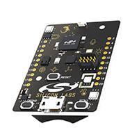


 工商网监
湘ICP备2023018690号
工商网监
湘ICP备2023018690号
