motionCookie™ SYSTEM IN A PACKAGE
motionCookie™
TMCC160-EVAL MANUAL
TMCC160 TMCL Hardware Version 1.1 | Document Revision 1.02 • 2017-OCT-06
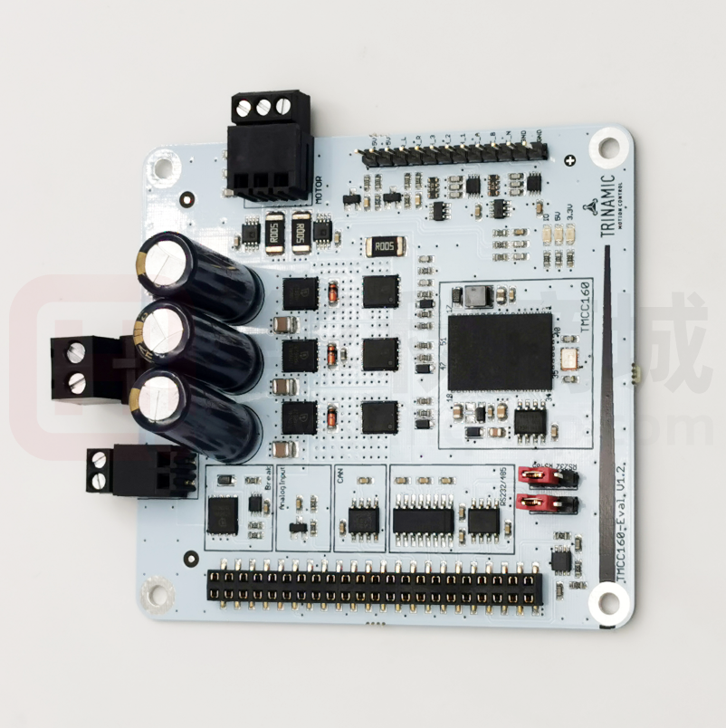
The TMCC160-EVAL is designed for evaluating all features of the TMCC160-LC motionCookie™.
The integrated ARM Cortex-M4 microcontroller is used to control one PMSM/BLDC axis. The
power MOSFETs are able to drive up to 10A (RMS) motor current. Several interfaces are
supported on the evaluation board (see features).
Features
• FOC torque-, velocity- and positioncontrol for PMSM/BLDC 3-phase motors
• Encoder and hall sensor-based operation
• Up to 10A RMS nominal motor current
• Supply voltage: +7V… +24V DC
operating voltage
• Interfaces: RS232, RS485, CAN, SPI™
• 2x reference switch inputs
• 1x analog input
Figure 1: TMCC160-EVAL
Applications
• Robotics
• Pump and Fan Applications
• Industrial Automation
• Medical
• Lab Automation
Block Diagram
Ref.
Switches
I_U, I_V
Power Bridge
TMCC160
VM
Motor
RS485
U
PWM
RS232
Microcontroller
CAN
SPI0
DIAG
Gatedriver
V
W
Current
AIN
ABN
Power
Supply
HALL
DC/DC
(3.3V)
ABN
HALL
I_U, I_V
Figure 2: Simplified Block Diagram
Order Code
Order code
TMCC160-EVAL
Description
Evaluation board for TMCC160 single axis BLDC controller.
Table 1: TMCC160 Order Code
SUPPLEM ENTAL DIRECTIVES
© 2015 TRINAMIC Motion Control GmbH & Co. KG, Hamburg,
Germany — Terms of delivery and rights to technical change
reserved. Download newest version at: www.trinamic.com .
Read entire documentation; especially the Supplemental
Directives.
Size
85 x 79 x 34
�TMCC160 TMCL Hardware Version 1.1 | Document Revision 1.02 • 2017-OCT-06
2/16
Read the entire documentation before you make use of this product:
•
•
•
Ensure you meet the Target User Requirements on page 13.
Read the User Information and Directives provided on page 13.
Read the ESD-Sensitivity Directives provided on page 13.
Keep this manual and all other applicable and related documents complete,
legible and accessible to the specified user at all times.
Failure to observe the Supplem ental Directives could result in damage to
product and things; to property or persons; or economic loss.
i
Contact
TRI NAM I C
support team
TRINAMIC is not liable for damages incurred as a result of improper use or
disregard of the instructions provided in this docum ent.
Please refer to our User I nform ation and Directives for more details (page
13).
In case you encounter difficulties or need additional advice, please contact our support
team via: www.trinamic.com. Thank you.
© 2015 TRINAMIC Motion Control GmbH & Co. KG, Hamburg, Germany — Terms of delivery and rights
to technical change reserved. Download newest version at: www.trinamic.com .
Read entire documentation; especially the Supplemental Directives.
�TMCC160 TMCL Hardware Version 1.1 | Document Revision 1.02 • 2017-OCT-06
3/16
TABLE OF CONTENTS
TMCC160-EVAL Manual......................................................................................... 1
Order Code ...................................................................................................................................... 1
SUPPLEMENTAL DIRECTIVES ............................................................................... 1
Contact TRINAMIC support team ...................................................................................................... 2
TABLE OF CONTENTS ............................................................................................ 3
1.1
1.2
1.3
2
3
Connector Overview ............................................................................................................. 4
LEDs ................................................................................................................................... 7
RS232, RS485 Interface Switch ............................................................................................. 8
Operational Ratings of TMCC160-EVAL........................................................... 9
Getting Started .............................................................................................. 10
Preparations .................................................................................................................................. 10
Start-up Preparations ..................................................................................................................... 11
Graphic Overview: Getting Started .................................................................................................. 11
USER INFORMATION AND DIRECTIVES ............................................................. 13
ESD-DEVICE INSTRUCTIONS .......................................................................................................... 13
Producer Information ..................................................................................................................... 13
Copyright ...................................................................................................................................... 13
Target User ................................................................................................................................... 13
Disclaimer: Life Support Systems .................................................................................................... 13
Disclaimer: Intended use ................................................................................................................ 13
TMCC160-EVAL Document Info ....................................................................................................... 14
Related Documents ........................................................................................................................ 14
Collateral documents ...................................................................................................................... 14
REVISION HISTORY ............................................................................................ 15
Hardware Product Revision History (HW V.) ..................................................................................... 15
REFERENCES ....................................................................................................... 15
Related Documents and Tools ......................................................................................................... 15
TABLE INDEX ...................................................................................................... 16
FIGURE INDEX .................................................................................................... 16
CLOSING NOTE ................................................................................................... 16
Hardware
© 2015 TRINAMIC Motion Control GmbH & Co. KG, Hamburg, Germany — Terms of delivery and rights
to technical change reserved. Download newest version at: www.trinamic.com .
Read entire documentation; especially the Supplemental Directives.
�TMCC160 TMCL Hardware Version 1.1 | Document Revision 1.02 • 2017-OCT-06
4/16
1.1 Connector Overview
Brake
1
Power
1
1
Motor
Interface
Encoder-, Hall-,
Ref. Switches
1
2
1
Figure 3: TMC160-EVAL Connectors
TMCC160-EVAL Connectors
Label
(Key)
Connector Type
Power
RIA 330-02, 2 pol., 5mm pitch,
shrouded header
Brake
RIA 182-02, 2 pol., 3.5mm pitch, header
Motor
RIA 182-03, 3 pol., 3.5mm pitch, header
Encoder-,
Hall-, Ref.
Switches
Standard male 12 pin connector, one
row, 2.54mm pitch
Mating Connector Type
RIA 349-2, screw type terminal block,
pluggable, centerline 5 mm / 0.197 inches,
wire entry parallel to plug direction
RIA 169-02, screw type terminal block,
pluggable, centerline 3.5 mm / 0.138 inches,
wire entry parallel to plug direction
RIA 169-03, screw type terminal block,
pluggable, centerline 3.5 mm / 0.138 inches,
wire entry parallel to plug direction
Standard female 12 pin connector, one row,
2.54mm pitch
© 2015 TRINAMIC Motion Control GmbH & Co. KG, Hamburg, Germany — Terms of delivery and rights
to technical change reserved. Download newest version at: www.trinamic.com .
Read entire documentation; especially the Supplemental Directives.
�TMCC160 TMCL Hardware Version 1.1 | Document Revision 1.02 • 2017-OCT-06
5/16
TMCC160-EVAL Connectors
Label
(Key)
Connector Type
2 x 22 pol., 2.54mm pitch, pluggable
female connector 2 x 22 pol., 2.54mm
pitch, pluggable male connector
Interface
Mating Connector Type
2 x 22 pol., 2.54mm pitch, pluggable female
connector 2 x 22 pol., 2.54mm pitch,
pluggable male connector
Table 2: TMC5031-EVAL Connectors
This connector fits for commercially available power supply units for e.g. 24V DC.
Power Connector
Pin
Label
Description
1
+VM
Power supply input +7V .. 24V DC
2
GND
System GND
Table 3: Power Connector
Brake Connector
Pin
Label
Description
1
2
Brake
+VM
Open collector brake output.
Power supply output
Table 4: Brake Connector
Motor Connector
Pin
1
2
3
Label
Description
W
V
U
Motor coil W
Motor coil V
Motor coil U
Table 5: Motor Connector
Encoder-, Hall-, Ref. Switches Connector
Pin
1
2
3
4
5
6
7
8
9
10
Label
GND
GND
ENC_N
ENC_B
ENC_A
HALL_1
HALL_2
HALL_3
REF_R
REF_L
Pull-up
4k7
4k7
4k7
4k7
4k7
4k7
3k3
3k3
Description
System GND
System GND
Encoder index channel input.
Encoder quadrature channel B input.
Encoder quadrature channel A input.
Hall signal 1 input.
Hall signal 2 input.
Hall signal 3 input.
Right reference switch input.
Left reference switch input.
© 2015 TRINAMIC Motion Control GmbH & Co. KG, Hamburg, Germany — Terms of delivery and rights
to technical change reserved. Download newest version at: www.trinamic.com .
Read entire documentation; especially the Supplemental Directives.
�TMCC160 TMCL Hardware Version 1.1 | Document Revision 1.02 • 2017-OCT-06
6/16
Encoder-, Hall-, Ref. Switches Connector
11
12
-
+5V
+5V
Supply output for encoder-, hall-sensors
Supply output for encoder-, hall-sensors
Table 6: Encoder-, Hall-, Reference Switches Connector
Interface Connector
Pin
1
2
3
4
5
6
7
Label
+VM
GND
GND
ID_CLK
ID_CH0
ID_CH1
8
ENABLE
9
10
11
12
13
14
15
16
17
18
19
20
21
22
23
24
25
26
27
28
29
30
31
32
33
34
35
36
37
38
39
40
41
42
43
RS485_BRS485_A+
RS232_TX
RS232_RX
CAN_H
CAN_L
AIN
CSN
SCLK
MOSI
MISO
GND
Description
Power supply.
System GND.
System GND.
STARTRAMPE: clock pulse test point.
Not used.
ID channel 0. Not used with TMCC160-EVAL.
ID channel 1. Used for automatic module detection.
TMCC160 enable signal. Use open collector output only to switch enable signal
to GND.
Not used.
Negative differential RS485 interface signal.
Not used.
Positive differential RS485 interface signal.
Not used.
RS232 interface output.
Not used.
RS232 interface input.
Not used.
CAN high interface signal.
Not used.
CAN low interface signal.
Not used.
10V analog input.
Not used.
Not used.
Not used.
Not used.
Not used.
Not used.
Not used.
SPI interface chip select signal. Low active.
SPI interface clock signal.
SPI interface master out slave in signal.
SPI interface master in slave out signal.
Not used.
Not used.
Not used.
Not used.
Not used.
Not used.
Not used.
Not used.
Not used.
System ground.
© 2015 TRINAMIC Motion Control GmbH & Co. KG, Hamburg, Germany — Terms of delivery and rights
to technical change reserved. Download newest version at: www.trinamic.com .
Read entire documentation; especially the Supplemental Directives.
�TMCC160 TMCL Hardware Version 1.1 | Document Revision 1.02 • 2017-OCT-06
7/16
Interface Connector
Pin
44
GND
Label
Description
System ground.
Table 7: Interface Connector
1.2 LEDs
The TMCC160-EVAL has three LEDs. Two of them indicate the digital 3.3V (LED1) and 5V (LED2) power
supply. The third LED is connected with the brake chopper output pin. Whenever the brake chopper is active
LED3 is on.
Figure 4: LEDs
© 2015 TRINAMIC Motion Control GmbH & Co. KG, Hamburg, Germany — Terms of delivery and rights
to technical change reserved. Download newest version at: www.trinamic.com .
Read entire documentation; especially the Supplemental Directives.
�TMCC160 TMCL Hardware Version 1.1 | Document Revision 1.02 • 2017-OCT-06
8/16
1.3 RS232, RS485 Interface Switch
TMCC160-EVAL board supports RS232 or RS485 interface. To switch between both two jumpers
have to be configured as described in the table below.
RS232, RS485 Interface Switch
Connector
PIN
Description
1-2
If pin 1 and 2 of the interface switch is connected, RS485 interface is active.
2-3
If pin 2 and 3 of the interface switch is connected, RS232 interface is active.
Table 8: RS232, RS485 Interface Switch
© 2015 TRINAMIC Motion Control GmbH & Co. KG, Hamburg, Germany — Terms of delivery and rights
to technical change reserved. Download newest version at: www.trinamic.com .
Read entire documentation; especially the Supplemental Directives.
�TMCC160 TMCL Hardware Version 1.1 | Document Revision 1.02 • 2017-OCT-06
9/16
2 Operational Ratings of TMCC160-EVAL
The operational ratings shown below should be used as design values. The maximum power
supply current depends on the used motors and the supply voltage.
AREAS OF
SPECIAL
CONCERN
!
Do not exceed the maximum values during operation! Otherwise the driver
will be damaged!
General Operational Ratings of the Module
Symbol
+VM
VAIN
Parameter
Power supply voltage for
operation
10V analog input voltage (24V
compatible)
Min
Type
Max
Unit
7
24
28
V
10
24
V
VENC_x
Encoder input signals
0
5
5.1
V
VHALL_x
Hall sensor input signals
0
5
5.1
V
VREF_x
Reference input signals
0
5
5.1
V
IMotor
Motor coil current [RMS]
ISUPPLY
Power supply current
TENV
Environment temperature at
rated current (no forced cooling
required)
10
A
10
20°C
Table 9: General Operational Ratings of the Module
© 2015 TRINAMIC Motion Control GmbH & Co. KG, Hamburg, Germany — Terms of delivery and rights
to technical change reserved. Download newest version at: www.trinamic.com .
Read entire documentation; especially the Supplemental Directives.
A
°C
�TMCC160 TMCL Hardware Version 1.1 | Document Revision 1.02 • 2017-OCT-06
10/1
6
3 Getting Started
Follow guidelines provided in this chapter:
•
•
•
Disconnect power supply.
Read safety instructions.
Follow configuration guidelines.
Failure to observe could result in damage to product and things; to property
or persons; or economic loss.
Preparations
You need:
•
•
•
•
•
•
TMCC160-EVAL
RS232, RS485, CAN interface
PMSM/BLDC motor
TMCL-IDE V3. And PC
Cables for interface, motor, and power supply
Nominal supply voltage +24V DC (+7…+24V DC)
Before You Connect the Devices
CAUTION
Minor injuries or unintended system behavior through incorrect
handling!
•
•
•
•
Do
Do
Do
Do
NOT
NOT
NOT
NOT
connect or disconnect the motor while still powered.
mix up connections and short-circuit pins.
bound I/O wires with motor wires.
exceed the maximum power supply of +28 DC.
Connect all devices according to specification and user manual
instructions in order to ensure safe handling and correct system
behavior.
© 2015 TRINAMIC Motion Control GmbH & Co. KG, Hamburg, Germany — Terms of delivery and rights
to technical change reserved. Download newest version at: www.trinamic.com .
Read entire documentation; especially the Supplemental Directives.
�11/1
6
TMCC160 TMCL Hardware Version 1.1 | Document Revision 1.02 • 2017-OCT-06
Start-up
Preparations
The following actions have to be carried out prior to start-up:
Action 1:
Download the TMCL-IDE 3.0 from www.trinamic.com and install it.
Result:
The TMCL-IDE then opens automatically.
Action 2:
Step 1: Connect one of the supported interfaces to the TMCC160-EVAL board.
Step 2: Connect a PMSM/BLDC motor with hall- or encoder sensor to the specific
connectors.
Step 3: Connect the +24V power supply to the TMCC160-EVAL board
Step 4: Turn power ON. The green LEDs one and two should turn ON
Step 5: Start TMCL-IDE V3.0 and select connected interface.
Result:
Now, all your connections have been established in order to start up the system,
NOTE:
→ Default interface settings:
RS232: 115.200 kbit/s
RS485: 115.200 kbit/s
CAN: 1Mbit/s
Graphic Overview: Getting Started
+24V Power
Supply
R
RS232
RS485
CAN
W
V
U
Motor
HALL 1, 2, 3
Encoder A, B, N
Encoder
Figure 5: Graphic Overview: Getting Started
TMCC160-EVAL Size and Mounting Holes
The board dimensions are 85mm x 79mm. Maximum component height (above PCB level)
without mating connectors is 32mm. There are four mounting holes suitable for M3 screws.
© 2015 TRINAMIC Motion Control GmbH & Co. KG, Hamburg, Germany — Terms of delivery and rights
to technical change reserved. Download newest version at: www.trinamic.com .
Read entire documentation; especially the Supplemental Directives.
�12/1
6
TMCC160 TMCL Hardware Version 1.1 | Document Revision 1.02 • 2017-OCT-06
79
85
4
4
Figure 6: TMCC160-EVAL Dimensions
© 2015 TRINAMIC Motion Control GmbH & Co. KG, Hamburg, Germany — Terms of delivery and rights
to technical change reserved. Download newest version at: www.trinamic.com .
Read entire documentation; especially the Supplemental Directives.
�TMCC160 TMCL Hardware Version 1.1 | Document Revision 1.02 • 2017-OCT-06
13/1
6
USER INFOR M ATION AND DIRECTIVES
ESD-DEVICE INSTRUCTIONS
This product is an ESD-sensitive CMOS device. It is sensitive to electrostatic
discharge.
•
•
•
Provide effective grounding to protect personnel and machines.
Ensure work is performed in a non-static environment.
Use personal ESD control footwear and ESD wrist straps, if necessary.
Failure to do so can result in defects, damages and decreased reliability.
Producer
Information
The producer of the product TMCC160 is TRINAMIC GmbH & Co. KG in Hamburg,
Germany; hereafter referred to as TRINAMIC. TRINAMIC is the supplier; and in this
function provides the product and the production documentation to its customers
Copyright
TRINAMIC owns the content of this user manual in its entirety, including but not
limited to pictures, logos, trademarks, and resources.
© Copyright 2015 TRINAMIC®. All rights reserved. Electronically published by
TRINAMIC®, Germany. All trademarks used are property of their respective owners.
Redistributions of source or derived format (for example, Portable Document Format
or Hypertext Markup Language) must retain the above copyright notice, and the
complete Datasheet User Manual documentation of this product including associated
Application Notes; and a reference to other available product-related documentation.
Target User
The documentation provided here, is for programmers and engineers only, who are
equipped with the necessary skills and have been trained to work with this type of
product.
The Target User knows how to responsibly make use of this product without causing
harm to himself or others, and without causing damage to systems or devices, in
which the user incorporates the product.
Disclaimer: Life
Support Systems
TRINAMIC Motion Control GmbH & Co. KG does not authorize or warrant any of its
products for use in life support systems, without the specific written consent of
TRINAMIC Motion Control GmbH & Co. KG.
Life support systems are equipment intended to support or sustain life, and whose
failure to perform, when properly used in accordance with instructions provided, can
be reasonably expected to result in personal injury or death.
Information given in this document is believed to be accurate and reliable. However,
no responsibility is assumed for the consequences of its use nor for any infringement
of patents or other rights of third parties which may result from its use. Specifications
are subject to change without notice.
Disclaimer:
Intended use
The data specified in this user manual is intended solely for the purpose of product
description. No representations or warranties, either express or implied, of
merchantability, fitness for a particular purpose or of any other nature are made
hereunder with respect to information/specification or the products to which
information refers and no guarantee with respect to compliance to the intended use
is given.
© 2015 TRINAMIC Motion Control GmbH & Co. KG, Hamburg, Germany — Terms of delivery and rights
to technical change reserved. Download newest version at: www.trinamic.com .
Read entire documentation; especially the Supplemental Directives.
�TMCC160 TMCL Hardware Version 1.1 | Document Revision 1.02 • 2017-OCT-06
14/1
6
In particular, this also applies to the stated possible applications or areas of
applications of the product. TRINAMIC products are not designed for and must not be
used in connection with any applications where the failure of such products would
reasonably be expected to result in significant personal injury or death (Safety-Critical
Applications) without TRINAMIC’s specific written consent.
TRINAMIC products are not designed nor intended for use in military or aerospace
applications or environments or in automotive applications unless specifically
designated for such use by TRINAMIC. TRINAMIC conveys no patent, copyright, mask
work right or other trade mark right to this product. TRINAMIC assumes no liability
for any patent and/or other trade mark rights of a third party resulting from processing
or handling of the product and/or any other use of the product.
TMCC160-EVAL
Document Info
This EVALBOARD User Manual contains only one document, which is the
document “EVALBOAR D User M anual. Section: Hardw are ”. It is made
available to you by TRINAMIC Motion Control GmbH & Co. KG in Hamburg,
Germany.
To access other Datasheets/User Manuals pertaining to TMCC160, please visit the
TMCC160 product page at www.trinamic.com .
Related
Documents
The TMCC160 DATASHEET User Manual is related to this product.
Collateral
documents
This product documentation comes with additional tool kits, firmware
and/or other items, as provided on the specified product page on our
company website.
i
They are made available to you for your convenience but are not part of the
TMCC160- EVALBOARD User Manual documentation.
© 2015 TRINAMIC Motion Control GmbH & Co. KG, Hamburg, Germany — Terms of delivery and rights
to technical change reserved. Download newest version at: www.trinamic.com .
Read entire documentation; especially the Supplemental Directives.
�TMCC160 TMCL Hardware Version 1.1 | Document Revision 1.02 • 2017-OCT-06
15/1
6
R EVISION HISTOR Y
Hardware Product Revision History (HW V.)
Version
1.1
Date
2015-OCT-16
Description
Initial version.
Table 10: Hardware Revision History
Hardware Document Revision History (DC Rev.)
Version
1.00
1.01
1.02
Date
2015-OCT-16
2016-JAN-04
2017-OCT-06
Author/s
JM/JP/SV
JP
JP
Description
Initial version.
Format Edits.
Table 3 lines swapped.
Table 11: Document Revision History
NOTE:
→ Please refer to associated documentation available on product webpage at www.trinamic.com.
R EFER ENCES
Related Documents and Tools
[TMCC160]
TMCC160 Datasheet (please refer to http://www.trinamic.com)
© 2015 TRINAMIC Motion Control GmbH & Co. KG, Hamburg, Germany — Terms of delivery and rights
to technical change reserved. Download newest version at: www.trinamic.com .
Read entire documentation; especially the Supplemental Directives.
�TMCC160 TMCL Hardware Version 1.1 | Document Revision 1.02 • 2017-OCT-06
16/1
6
TABLE INDEX
Table
Table
Table
Table
Table
Table
Table
Table
Table
Table
Table
1: TMCC160 Order Code ................................................................................................................. 1
2: TMC5031-EVAL Connectors ........................................................................................................ 5
3: Power Connector ....................................................................................................................... 5
4: Brake Connector ........................................................................................................................ 5
5: Motor Connector ........................................................................................................................ 5
6: Encoder-, Hall-, Reference Switches Connector ............................................................................ 6
7: Interface Connector ................................................................................................................... 7
8: RS232, RS485 Interface Switch ................................................................................................... 8
9: General Operational Ratings of the Module .................................................................................. 9
10: Hardware Revision History ...................................................................................................... 15
11: Document Revision History ..................................................................................................... 15
FIGUR E INDEX
Figure
Figure
Figure
Figure
Figure
Figure
1: TMCC160-EVAL ......................................................................................................................... 1
2 Block Diagram: .......................................................................................................................... 1
4: TMC160-EVAL Connectors ......................................................................................................... 4
5: LEDs ........................................................................................................................................ 7
6: Graphic Overview: Getting Started ........................................................................................... 11
7: TMCC160-EVAL Dimensions ..................................................................................................... 12
CLOSING NOTE
© TRINAMIC Motion Control GmbH & Co. KG 2015
Information given in this data sheet is believed to be accurate
and reliable. However, neither responsibility is assumed for
the consequences of its use nor for any infringement of
patents or other rights of third parties, which may result from
its use.
Specifications are subject to change without notice.
© 2015 TRINAMIC Motion Control GmbH & Co. KG, Hamburg, Germany — Terms of delivery and rights
to technical change reserved. Download newest version at: www.trinamic.com .
Read entire documentation; especially the Supplemental Directives.
�


 工商网监
湘ICP备2023018690号
工商网监
湘ICP备2023018690号
