SK102 THRU SK1010
SURFACE MOUNT SCHOTTKY BARRIER RECTIFIER
Forward Current - 10.0 Amperes
Reverse Voltage - 20 to 100 Volts
FEATURES
DO-214AB/SMC
The plastic package carries Underwriters Laboratory
Flammability Classification 94V-0
For surface mounted applications
Low reverse leakage
Built-in strain relief,ideal for automated placement
High forward surge current capability
High temperature soldering guaranteed:
250 C/10 seconds at terminals
0.245(6.22)
0.220(5.59)
0.126 (3.20)
0.114 (2.90)
0.280(7.11)
0.260(6.60)
0.012(0.305)
0.006(0.152)
0.103(2.62)
0.079(2.06)
MECHANICAL DATA
0.060(1.52)
0.030(0.76)
Case: JEDEC DO-214AB molded plastic body
Terminals: Solder plated, solderable per MIL-STD-750,
Method 2026
Polarity: Color band denotes cathode end
Mounting Position: Any
Weight:0.007 ounce, 0.25grams
0.008(0.203)MAX.
0.320(8.13)
0.305(7.75)
Dimensions in inches and (millimeters)
MAXIMUM RATINGS AND ELECTRICAL CHARACTERISTICS
Ratings at 25 C ambient temperature unless otherwise specified.
Single phase half-wave 60Hz,resistive or inductive load,for capacitive load current derate by 20%.
MDD Catalog Number
Maximum repetitive peak reverse voltage
Maximum RMS voltage
Maximum DC blocking voltage
Maximum average forward rectified current
at TL =95 C
Peak forward surge current
8.3ms single half sine-wave superimposed on
rated load (JEDEC Method)
Maximum instantaneous forward voltage at 10.0A
Maximum DC reverse current
TA=25 C
at rated DC blocking voltage
TA=100 C
Typical junction capacitance (NOTE 1)
Typical thermal resistance (NOTE 2)
Operating junction temperature range
Storage temperature range
SYMBOLS SK102 SK103 SK1035 SK104 SK1045 SK106 SK108
VRRM
VRMS
VDC
20
14
20
30
21
30
35
24.5
35
40
28
40
45
31.5
45
60
42
60
80
56
80
SK1010 UNITS
100
70
100
VOLTS
VOLTS
VOLTS
I(AV)
10.0
Amps
IFSM
250.0
Amps
VF
IR
CJ
RθJA
TJ,
TSTG
Note: 1.Measured at 1MHz and applied reverse voltage of 4.0V D.C.
2.P.C.B. mounted with 0.2x0.2 ”(5.0x5.0mm) copper pad areas
0.65
0.85
1
20
500
18.0
-50 to +150
-50 to +150
Volts
mA
pF
C/W
C
C
�RATINGS AND CHARACTERISTIC CURVES SK102 THRU SK1010
Figure 1
Typical Forward Characteristics
100
Figure 2
Forward Derating Curve
600
12
400
10
200
100
8.0
60
6.0
40
20
Amps
Amps
SK102-SK1045
4.0
SK105-SK1010
10
2.0
6
4
0
Single Phase, Half Wave
60Hz Resistive or Inductive Load
60
80
100
2
120
140
160
°C
25°C
1
Average Forward Rectified Current - Amperes
versus Lead Temperature - C
.6
.4
.2
.1
180
.2
.4
.6
.8
1.0
1.4
1.2
Volts
Instantaneous Forward Current - Amperes versus
Instantaneous Forward Voltage - Volts
Figure 3
Junction Capacitance
100
600
400
200
pF
TJ =25°C
100
60
40
20
10
.1
.2
.4
1
Volts
2
4
10
20
40
100 200
400
Junction Capacitance - pF versus
Reverse Voltage - Volts
The cruve graph is for reference only, can't be the basis for judgment(曲线图仅供参考)!
1000
�RATINGS AND CHARACTERISTIC CURVES SK102 THRU SK1010
Figure 4
Typical Reverse Characteristics
Figure 5
Peak Forward Surge Current
600
10
500
6
4
400
2
300
100°C
Amps
1
200
.6
100
.4
mAmps
0
.2
1
2
4
6 8 10 20
40
60 80 100
75°C
Cycles
mAmps .1
Peak Forward Surge Current - Amperes versus
Number Of Cycles At 60Hz - Cycles
.06
.04
.02
25°C
SK102-SK1045
SK105-SK1010
.01
.006
.004
.002
.001
20
40
60
80
100
120
140
Volts
Instantaneous Reverse Leakage Current - MicroAmperes versus
Percent Of Rated Peak Reverse Voltage - Volts
The cruve graph is for reference only, can't be the basis for judgment(曲线图仅供参考)!
�
很抱歉,暂时无法提供与“SK1010-SMC”相匹配的价格&库存,您可以联系我们找货
免费人工找货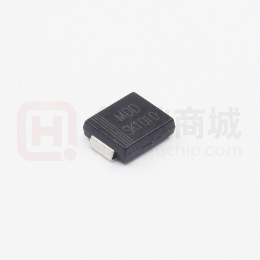


 工商网监
湘ICP备2023018690号
工商网监
湘ICP备2023018690号
