Ultrasonic
Diffuse, Analogue and Digital Output
Types UA30CAD......TI
• Cylindrical M30 PBT housing
• Sensing distance: 250-3500 mm
• Power supply: 12 (15) to 30 VDC
• Outputs: 0-10 VDC or 4-20 mA and one switching
output NPN or PNP.
• Linearity error 0.5%
• Repeatability 0.2%
• Beam angle. ±6°
• Protection: Short-circuit, reverse polarity and
overvoltage
• Protection degree IP 67, Nema 4X
• 2 m cable or M12 plug
Product Description
Ordering Key
A family of diffuse ultrasonic
sensors with sensing range
from 250-3500 mm with a
resolution as low as 2.0 mm.
The sensor contains both an
analogue and a digital output.
The output is either 0-10V or
4-20 mA and the digital output
NPN or PNP, NO or NC which
forms a windows detection.
Ultrasonic sensor
Housing style
Housing size
Housing material
Housing length
Detection principle
Sensing distance
Output type
Output configuration
Connection
Teach-in
The sensor is the ideal choice
for distance measurement,
level measurement, diameter
measurement or loop control.
Due to use of microprocessor control the digital filtering
makes the sensor immune to
most electromagnetic inter
ferences.
UA30CAD35NGM1TI
Type Selection
Housing
diameter
Connec-
tion
Rated operating
dist. (Sn)
Analog
Digital output
Ordering no.
Output NPN/PNP
M30
M30
M30
M30
M30
M30
M30
M30
Plug M12
Cable
Plug M12
Cable
Plug M12
Cable
Plug M12
Cable
250-3500
250-3500
250-3500
250-3500
250-3500
250-3500
250-3500
250-3500
4-20
4-20
0-10
0-10
4-20
4-20
0-10
0-10
mm
mm
mm
mm
mm
mm
mm
mm
mA
mA
V
V
mA
mA
V
V
NPN
NPN
NPN
NPN
PNP
PNP
PNP
PNP
UA
UA
UA
UA
UA
UA
UA
UA
30
30
30
30
30
30
30
30
CAD
CAD
CAD
CAD
CAD
CAD
CAD
CAD
35
35
35
35
35
35
35
35
NG M1 TI
NG TI
NK M1 TI
NK TI
PG M1 TI
PG TI
PK M1 TI
PK TI
Specifications
Rated operating distance (Sn) Reference target: 1 mm
metal rolled finish, size
200 x 200 mm.
250 - 3500 mm
Blind zone
≤ 250 mm
Repeatability
0.2%
Linearity error
0.5%
Beam angle
±6˚
Sensitivity
Push-button
P1 (longest setpoint)
P2 (shortest setpoint)
Resolution
2 mm
Temperature drift 0.1%/˚C @ -20˚ to +70˚ C
Temperature compensation Yes
Hysteresis (H)
Min. 0.5%
Specifications are subject to change without notice (12.05.2014)
Rated operational voltage (UB)
NG or PG versions
12 to 30 VDC
NK or PK versions
15 to 30 VDC
(ripple included)
Ripple (Urpp)
≤ 5%
No-load supply current (Io)
50 mA @ UB max
Output current continuous
digital output (Ie)
Max. load capacity 100 nF
100 mA
Output current short-time
digital output (I)
Max. load capacity 100 nF
100 mA
Minimum operational current
digital output (Im)
0.5 mA
OFF-state current digital
output (Ir)
10 μA
1
�UA30CAD..
Specifications (cont.)
Voltage drop digital output (Ud) ≤ 2.2 VDC @ 100 mA
Protection
Digital output
Short-circuit, overvoltage
pulses and reverse polarity
Supply
Overvoltage pulses and
reverse polarity
Analogue output
Overvoltage pulses
Analog output
NG.. or PG.. types
4 to 20 mA
NK.. or PK.. types
0 to 10 VDC
Load
4 to 20 mA
max. 500 Ω
0 to 10 VDC
min. 3 kΩ
Carrier frequency
112 kHz
Operating frequency digital
output (f)
≤ 2 Hz
Response time OFF-ON
digital output (tON)
≤ 250 mS
Response time ON-OFF
digital output (tOFF)
≤ 250 mS
Response time analog output ≤ 500 mS
Power ON delay
≤ 500 mS
Output function, open
collector
By sensor type
NPN or PNP
Output switching function
One open collector transis-
tor and one analogue
output to be configured as:
- Windows function with
N.O or N.C. output.
- Analogue output with
positive or negative slope.
Indication
Output ON
Yellow LED
Echo received
Green LED
Environment
Installation category
Pollution degree
Degree of protection
Ambient temperature
Operating
Storage
Vibration
Shock
Rated insulation voltage
Housing
Material body
Material front
Material back, plug
Material back, cable
Material push-button
Sealing around push-button
Material sealing front
Connection
Cable
Plug
Tightening torque
Weight
Cable version
Plug version
CE-marking
Approvals
Wiring Diagram
Detection Range
lll (IEC 60664/60664A;
60947-1)
3 (IEC 60664/60664A;
60947-1)
IP67 (IEC 60529; 60947-1)
Nema 4X
-20° to +70°C (-4° to +158°F)
-35° to +70°C (-31° to +158°F)
10 to 55 Hz, 1.0 mm/6G.
(IEC/EN 60068-2-6)
30 g / 11 mS, 3 directions
(IEC/EN 60068-2-27)
< 500 VAC (rms)
PBT
Epoxy-glass resin
Grilamid
Grilamid
TPE
TPE
TPE
PVC, grey, 2 m,
4 x 0.34 mm2, Ø = 4.7 mm
M12, 4-pin (CON. 14-series)
≤ 1.5 Nm
160 g
90 g
Yes
cULus (UL508)
X
U
BK4
BU3
Voltage
BN1
NPN:
U BK4
WH2
BU3
I
400
BK4
BU3
Current
BN1
I BK4
WH2
BU3
Y
Sensor
Parallel displacement (mm)
PNP:
Target
0
1.6
3.3
Distance (feet)
4.9
6.6
8.2
9.8
11.5
15.7
300
11.8
200
7.9
100
3.9
0
0
-100
-3.9
-200
-7.9
-300
-11.8
-400
0
0.5
1.0
1.5
2.0
2.5
3.0
3.5
Parallel displacement (inch)
BN1
WH2
BN1
WH2
-15.7
Distance (m)
2
Specifications are subject to change without notice (12.05.2014)
�Green
89.8
69.6
Teach
M 12 x 1 - 6g
Yellow
M 30 x 1.5 - 6g
UA30CAD..
Teach
10
10 3
Green
Teach
Teach
Yellow
89.8
69.6
Teach
Green
O 4.7
Yellow
89.8
69.6
M 12 x 1 - 6g
Teach
Cable
M 30 x 1.5 - 6g
Plug
M 30 x 1.5 - 6g
Dimensions
10
10
10 3
3
Teach
M 30 x 1.5 - 6g
Programming setup
89.8
69.6
Teach
General
set up
Yellow
Greenof sensing point P1 (longest distance) and Shortest distance (P2) independent on the sensor type or
function.
O 4.7
1) Mount the sensor in the selected application
2) Place a target in front of the sensor at the maximum required distance (P1), then press shortly on the teach-button,
10
3
the Yellow LED switch Off
and
then On again after maximum 2 seconds. The distance (P1) is now saved in the
sensor, and the target can be moved. I)
3) Place the target at the minimum distance requested (P2), then press shortly on the teach-button, the yellow LED
turn Off then flash 5 times . The distance (P2) is now saved in the sensor and the target can be moved. II)
I) P1 can be set to a maximum exceeding the family specification for the sensor by removing the target in front of
the sensor, push and hold the teach-button more than one second and the sensing distance is set at a unique
distance for this sensor only. Do not use this function for an analogue output.
II) The second switch point can be set to minimum by setting the target within the blind zone close to the sensor
head or by covering the sensor head with your hand while teaching P2.
Sensors with 1 digital output and one analogue output UA..CAD..PG/PK/NG or NK types
1) The factory setting is Normally Open N.O. for the digital output and positive slope for the analogue output.
Digital output
distance
2) To reverse the slope to negative and reverse the N.O. output to Normally Closed N.C. Push the teach-button for 8
second until the yellow LED flash fast release the teach button and the LED will flash 5 times to acknowledge the
change in function.
Digital output
3) To switch back to positive slope or N.O. output, repeat step 2.
Specifications are subject to change without notice (12.05.2014)
3
�Installation Hints
To avoid interference from inductive voltage/
current peaks, separate the prox. switch
power cables from any other power cables,
e.g. motor, contactor or solenoid cables
Relief of cable strain
Protection of the sensing face
Switch mounted on mobile carrier
A proximity switch should not serve as
mechanical stop
Any repetitive flexing of the
cable should be avoided
Incorrect
Correct
The cable should not be pulled
Delivery Contents
Accessories
• Ultrasonic sensor: UA30CAD....
• Installation instruction
• Mounting:
2 x M30 Nuts
2 x rubber washers
• Packaging: Carton box 35 x 107 x 173 mm
• Connector type CONM14NF.. series
4
Specifications are subject to change without notice (12.05.2014)
�
很抱歉,暂时无法提供与“UA30CAD35NPM1TI”相匹配的价格&库存,您可以联系我们找货
免费人工找货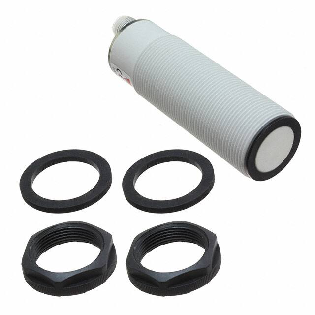


 工商网监
湘ICP备2023018690号
工商网监
湘ICP备2023018690号
