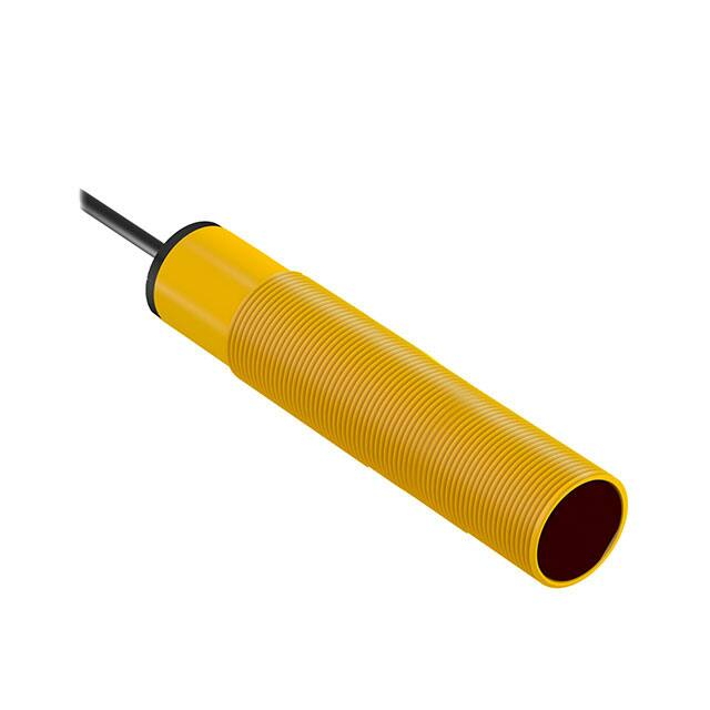
S18 Series Sensor (AC Voltage)
Instruction Manual
•
•
•
•
Featuring EZ-BEAM® technology for reliable sensing without the need for
adjustments
Completely epoxy-encapsulated to provide superior durability, designed to
meet rigorous IP69K standards for use in 1200 psi washdowns
Innovative dual-indicator system for simple sensor performance monitoring
20 V AC to 250 V AC (3-wire connection); SPST solid-state switch output,
maximum load 300 mA
WARNING:
• Do not use this device for personnel protection
• Using this device for personnel protection could result in serious injury or death.
• This device does not include the self-checking redundant circuitry necessary to allow its use in
personnel safety applications. A device failure or malfunction can cause either an energized (on) or deenergized (off) output condition.
Models
Sensing Mode
Range
LED
Output
-
S183E
20 m (66 ft)
Infrared 950 nm
LO
S18AW3R
DO
S18RW3R
LO
S18AW3L
DO
S18RW3L
LO
S18AW3LP
DO
S18RW3LP
OPPOSED
2 m (79 in)
Infrared 950 nm
2 m (79 in)
Visible Red 680 nm
RETRO
P
POLAR RETRO
1
100 mm (4 in)
Infrared 880 nm
DIFFUSE
300 mm (12 in)
25 mm (1 in) cutoff
50 mm (2 in) cutoff
Infrared 880 nm
FIXED-FIELD
100 mm (4 in) cutoff
Model
LO
S18AW3D
DO
S18RW3D
LO
S18AW3DL
DO
S18RW3DL
LO
S18AW3FF25
DO
S18RW3FF25
LO
S18AW3FF50
DO
S18RW3FF50
LO
S18AW3FF100
DO
S18RW3FF100
Standard 2 m (6.5 ft) cable models are listed.
• To order the 9 m (30 ft) cable models, add suffix W/30 (for example, S183E W/30).
• To order the 4-pin 1/2"-20UNF QD models, add suffix Q1 (for example, S183EQ1). A model with a QD connector requires a
mating cable.
• To order the 5-pin 1/2"-20UNF QD models, add suffix Q (for example, S183EQ). A model with a QD connector requires a
mating cable.
1 Use polarized models when shiny objects will be sensed.
Original Document
121521 Rev. D
5 April 2021
121521
�S18 Series Sensor (AC Voltage)
Fixed-Field Mode Overview
S18 self-contained fixed-field sensors are small, powerful, infrared diffuse
mode sensors with far-limit cutoff (a type of background suppression). Their
high excess gain and fixed-field technology allow them to detect objects of low
reflectivity, while ignoring background surfaces.
Receiver
The cutoff distance is fixed. Backgrounds and background objects must always
Elements
be placed beyond the cutoff distance.
Near R1
The S18FF compares the reflections of its emitted light beam (E) from an
Detector
object back to the sensor’s two differently aimed detectors, R1 and R2. If the
near detector (R1) light signal is stronger than the far detector (R2) light signal
Far
(see object A, closer than the cutoff distance), the sensor responds to the
R2
Detector
object. If the far detector (R2) light signal is stronger than the near detector
(R1) light signal (see object B, beyond the cutoff distance), the sensor ignores
the object.
Emitter
Figure 1. Fixed-field concept
Cutoff
Distance
Object B
or
Background
Object
A
Lenses
E
Sensing
Range
Object is sensed if amount of light at R1
is greater than the amount of light at R2
The cutoff distance for model S18FF sensors is fixed at 25, 50 or 100 millimeters (1 in, 2 in, or 4 in). Objects lying beyond the cutoff
distance usually are ignored, even if they are highly reflective. However, it is possible to falsely detect a background object, under
certain conditions (see Background Reflectivity and Placement).
In the drawings and discussion on these pages, the letters E, R1, and R2 identify how the sensor’s three optical elements (Emitter
“E”, Near Detector “R1”, and Far Detector “R2”) line up across the face of the sensor. The location of these elements defines the
sensing axis (see Figure 2 on p. 2). The sensing axis becomes important in certain situations, such as those illustrated in Figure
5 on p. 3 and Figure 6 on p. 3.
Sensor Setup
Sensing Reliability
As a general rule, the most reliable sensing of an object approaching from the side occurs when the line of approach is parallel to
the sensing axis.
For highest sensitivity, position the target object for sensing at or near the point of
maximum excess gain. The excess gain curves for these products are shown.
Maximum excess gain for the 25 mm models occurs at a lens-to-object distance of
about 7 mm; for 50 mm models, at about 10 mm; and for the 100 mm models, at
about 20 mm. Sensing at or near this distance will make maximum use of each
sensor’s available sensing power. The background must be placed beyond the
cutoff distance. (Note that the reflectivity of the background surface also may affect
the cutoff distance.) Following these two guidelines will improve sensing reliability.
Figure 2. Fixed-field sensing axis
E
Sensing
Axis
R2
R1
Background Reflectivity and Placement
Avoid mirror-like backgrounds that produce specular reflections. False sensor response will occur if a background surface reflects
the sensor’s light more strongly to the near detector, or “sensing” detector (R1), than to the far detector, or “cutoff” detector (R2). The
result is a false ON condition (see Figure 3 on p. 3). To cure this problem, use a diffusely reflective (matte) background, or angle
either the sensor or the background (in any plane) so the background does not reflect light back to the sensor (see Figure 4 on p.
3). Position the background as far beyond the cutoff distance as possible.
An object beyond the cutoff distance, either stationary (and when positioned as shown in Figure 5 on p. 3), or moving past the
face of the sensor in a direction perpendicular to the sensing axis, can cause unwanted triggering of the sensor if more light is
reflected to the near detector than to the far detector. The problem is easily remedied by rotating the sensor 90° (Figure 6 on p.
3). The object then reflects the R1 and R2 fields equally, resulting in no false triggering. A better solution, if possible, may be to
reposition the object or the sensor.
2
www.bannerengineering.com - Tel: + 1 888 373 6767
P/N 121521 Rev. D
�S18 Series Sensor (AC Voltage)
Figure 4. Reflective Background - Solution
Figure 3. Reflective Background - Problem
R1 = Near Detector
R2 = Far Detector
E = Emitter
Fixed Sensing
Field
Reflective
Background
S18FF
R1
R2
E
Cutoff
Distance
Cutoff
Distance
Strong
direct
reflection
to R1
S18FF
R1
Core of
emitted
beam
R2
E
Core of
Emitted
Beam
Strong
Direct
Reflection
Away From
Sensor
R1 = Near Detector
R2 = Far Detector
E = Emitter
Fixed
Sensing
Field
Figure 5. Object Beyond Cutoff - Problem
Figure 6. Object Beyond Cutoff - Solution
Cutoff
Distance
S18FF
Reflective
Background
Cutoff
Distance
S18FF
R1
R2
E
E, R1, R2
Fixed
Sensing
Field
Fixed
Sensing
Field
Reflective
Background
or Moving Object
R1 = Near Detector
R2 = Far Detector
E = Emitter
E = Emitter
R1 = Near Detector
R2 = Far Detector
A reflective background object in this position or moving across the
sensor face in this axis and direction may cause false sensor response.
Reflective
Background
or Moving Object
A reflective background object in this position or moving across the
sensor face in this axis will be ignored.
Color Sensitivity
The effects of object reflectivity on cutoff distance, though small, may be important for some applications. It is expected that at any
given cutoff setting, the actual cutoff distance for lower reflectance targets will be slightly shorter than for higher reflectance targets
(see Performance Curves). This behavior is known as color sensitivity.
For example, an excess gain of 1 for an object that reflects 1/10 as much light as the 90% white card is represented by the
horizontal graph line at excess gain = 10. An object of this reflectivity results in a far limit cutoff of approximately 20 mm (0.8 inches),
for the 25 mm (1 inch) cutoff model for example; thus 20 mm represents the cutoff for this sensor and target.
These excess gain curves were generated using a white test card of 90% reflectance. Objects with reflectivity of less than 90%
reflect less light back to the sensor, and thus require proportionately more excess gain in order to be sensed with the same reliability
as more reflective objects. When sensing an object of very low reflectivity, it may be especially important to sense it at or near the
distance of maximum excess gain.
Wiring
Figure 7. Cabled emitters
Figure 8. 4-pin 1/2"-20UNF QD emitters
bn (1)
rd/bk
bn (1)
+
bu (3)
20–250 V AC
−
rd/wh
20-250 V ac
bu (5)
20–250 V AC
bk (4)
rd
gn
Figure 9. 5-pin 1/2"-20UNF QD emitters
No Connection
wh (2)
No Connection
ye (3)
P/N 121521 Rev. D
www.bannerengineering.com - Tel: + 1 888 373 6767
3
�S18 Series Sensor (AC Voltage)
Figure 10. All other cabled models
bn (1)
rd/bk
−
rd/wh
rd
Load
gn
Figure 12. All other 5-pin 1/2"-20UNF QD Models
bn (1)
+
20–250 V AC
bu (3)
bk (4)
Figure 11. All other 4-pin 1/2"-20UNF QD Models
20–250 V AC
bu (5)
20-250 V ac
bk (4)
Load
Load
wh (2)
No Connection
No Connection
ye (3)
Specifications
Supply Voltage and Current
20 to 250 V AC (50/60 Hz)
Average current: 20 mA
Peak current: 200 mA at 20 V AC, 500 mA at 120 V AC, 750 mA at 250 V AC
Supply Protection Circuitry
Protected against transient voltages
Output Configuration
SPST solid-state AC switch; Three-wire connections; Choose light operate or
dark operate models
Light Operate: Output conducts when sensor sees its own (or the emitter’s)
modulated light
Dark Operate: Output conducts when the sensor sees dark
Indicators
Two LEDs (green and amber)
Green on: power to sensor is on
Amber on: sensor sees light
Amber flashing: excess gain marginal (1 to 1.5×) in light condition
Output Rating
300 mA maximum (continuous)
Fixed-field models: derate 5 mA/°C above +50 °C (+122 °F)
Inrush Capability 1 amp for 20 milliseconds, non-repetitive
OFF-state leakage current: < 100 microamps
ON-state saturation voltage: 3 V at 300 mA AC; 2 V at 15 mA AC
Construction
Housing: PBT polyester housing
Lens: polycarbonate (opposed-mode) or acrylic (other models)
Output Protection Circuitry
Protected against false pulse on power-up
Connections
2 m (6.5 ft) integral cable; 9 m (30 ft) integral cable; 4-pin 1/2"-20UNF quickdisconnect fitting; or 5-pin 1/2"-20UNF quick-disconnect fitting
Output Response Time
Opposed mode models: 16 ms ON, 8 ms OFF
Other models: 16 ms ON and OFF
NOTE: 100 ms delay on power-up
Repeatability
Opposed mode models: 2 ms
Other models: 4 ms
Repeatability and response are independent of signal strength.
Operating Conditions
–40 °C to +70 °C (–40 °F to +158 °F)
90% at +50 °C maximum relative humidity (non-condensing)
Environmental Rating
Leakproof design rated NEMA 6P and IEC IP67 per IEC 60529
IP69K per DIN40050 for quick disconnect and cable models when the cables
are protected from direct spray
Vibration and Mechanical Shock
All models meet MIL-STD-202F, Method 201A (Vibration: 10 Hz to 60 Hz
maximum, 0.06 inch (1.52 mm) double amplitude, 10G acceleration)
requirements.
Method 213B conditions H&I.
Shock: 75G with device operating; 100G for non-operation
Certifications
4
Required Overcurrent Protection
WARNING: Electrical connections must be
made by qualified personnel in accordance with
local and national electrical codes and
regulations.
Overcurrent protection is required to be provided by end product application
per the supplied table.
Overcurrent protection may be provided with external fusing or via Current
Limiting, Class 2 Power Supply.
Supply wiring leads < 24 AWG shall not be spliced.
For additional product support, go to www.bannerengineering.com.
Supply Wiring (AWG)
Required Overcurrent Protection (Amps)
20
5.0
22
3.0
24
2.0
26
1.0
28
0.8
30
0.5
www.bannerengineering.com - Tel: + 1 888 373 6767
P/N 121521 Rev. D
�S18 Series Sensor (AC Voltage)
Performance Curves
Opposed Mode
Excess Gain
1000
E
X
C
E
S
S
Beam Pattern
S18 Series
S18 Series
1500 mm
Opposed Mode
100
40"
500 mm
20"
0
G
A
I
N
10
1
0.1 m
(0.33')
1m
(3.3')
10 m
(33')
0
500 mm
20"
1000 mm
40"
1500 mm
60"
0
100 m
(330')
5m
(16')
Retroreflective Mode
1000
G
A
I
N
S18 Series
120 mm
Non-Polarized Retro
4.7"
Non-Polarized Retro
80 mm
3.2"
40 mm
with BRT-3 Reflector
1.6"
0
10
0.1 m
(0.33')
1m
(3.3')
1.6"
80 mm
3.2"
120 mm
4.7"
0
10 m
(33')
0.5 m
(1.6')
1.0 m
(3.2')
1.5 m
(4.8')
2.0 m
(6.4')
2
Beam Pattern
S18 Series
S18 Series
150 mm
Polarized Retro
100
6"
Polarized Retro
100 mm
4"
50 mm
10
0.1 m
(0.33')
1m
(3.3')
2"
0
with BRT-3 Reflector
1
0.01 m
(0.033')
2.5 m
(8.0')
DISTANCE
Excess Gain
1000
0
with BRT-3 Reflector
40 mm
Polarized Retroreflective Mode
G
A
I
N
25 m
(82')
Beam Pattern
DISTANCE
E
X
C
E
S
S
20 m
(66' )
S18 Series
100
1
0.01 m
(0.033')
15 m
(49')
2
Excess Gain
E
X
C
E
S
S
10 m
(32')
DISTANCE
DISTANCE
10 m
(33')
0
with BRT-3 Reflector
50 mm
2"
100 mm
4"
150 mm
6"
0
DISTANCE
2
60"
Opposed Mode
1000 mm
0.5 m
(1.6')
1.0 m
(3.2')
1.5 m
(4.8')
2.0 m
(6.4')
2.5 m
(8.0')
DISTANCE
Performance based on use of a model BRT-3 retroreflector (3" diameter). Actual sensing range may be more or less than specified, depending on the
efficiency and reflective area of the retroreflector used.
P/N 121521 Rev. D
www.bannerengineering.com - Tel: + 1 888 373 6767
5
�S18 Series Sensor (AC Voltage)
Diffuse 100 mm Mode
3
Excess Gain
1000
E
X
C
E
S
S
Beam Pattern
S18 Series
S18 Series
15 mm
Short Range
Diffuse Mode
100
10 mm
0.4"
5 mm
0.2"
Maximum Gain
G
A
I
N
0
10
Minimum Gain
1
1 mm
(0.04")
10 mm
(0.4")
100 mm
(4")
0.6"
Short Range Diffuse
0
5 mm
0.2"
10 mm
0.4"
15 mm
0.6"
0
1000 mm
(40")
25 mm
(1")
50 mm
(2")
DISTANCE
75 mm
(3")
100 mm 125 mm
(4")
(5")
DISTANCE
Diffuse 300 mm Mode 3
Excess Gain
1000
E
X
C
E
S
S
G
A
I
N
Beam Pattern
S18 Series
S18 Series
Long Range Diffuse
15 mm
100
Long Range
Diffuse Mode
Maximum Gain
0.4"
5 mm
0.2"
0
Minimum Gain
10 mm
(0.4")
100 mm
(4")
0
5 mm
0.2"
10 mm
0.4"
15 mm
0.6"
10
1
1 mm
(0.04")
0
1000 mm
(40")
80 mm
(3")
160 mm
(6")
DISTANCE
3
50 mm Mode
100 mm Mode
Excess Gain
Excess Gain
Excess Gain
1000
S18 Series
E
X
C
E
S
S
Fixed-field mode
with 25 mm far
limit cutoff
100
G
A
I
N
10
1
0.1 mm
(0.004")
320 mm 400 mm
(15")
(12")
25 mm Mode
1000
G
A
I
N
240 mm
(9")
DISTANCE
Fixed-Field
E
X
C
E
S
S
0.6"
10 mm
1 mm
(0.04")
10 mm
(0.4")
100 mm
(4")
E
X
C
E
S
S
Fixed-field mode
with 50 mm far
limit cutoff
100
10
1
0.1 mm
(0.004")
G
A
I
N
1 mm
(0.04")
10 mm
(0.4")
Using 18% gray test card: Cutoff distance
will be 90% of value shown. Using 6%
black test card: Cutoff distance will be
85% of value shown.
Ø 10 mm spot size @ 10 mm focus
Ø 10 mm spot size @ 50 mm cutoff
S18 Series
Fixed-field mode
with 100 mm far
limit cutoff
100
10
1
0.1 mm
(0.004")
100 mm
(4")
DISTANCE
DISTANCE
Using 18% gray test card: Cutoff distance
will be 95% of value shown. Using 6%
black test card: Cutoff distance will be
90% of value shown.
Ø 10 mm spot size @ 8 mm focus
Ø 10 mm spot size @ 25 mm cutoff
1000
S18 Series
1 mm
(0.04")
10 mm
(0.4")
100 mm
(4")
DISTANCE
Using 18% gray test card: Cutoff distance
will be 85% of value shown. Using 6% black
test card: Cutoff distance will be 75% of
value shown.
Ø 10 mm spot size @ 20 mm focus
Ø 10 mm spot size @ 100 mm cutoff
Focus and spot sizes are typical.
3
6
Performance based on use of a 90% reflectance white test card.
www.bannerengineering.com - Tel: + 1 888 373 6767
P/N 121521 Rev. D
�S18 Series Sensor (AC Voltage)
Dimensions
Cabled Models
QD Models
Yellow LED
Output Indicator
Yellow LED
Output Indicator
Green LED
Power Indicator
Green LED
Power Indicator
85.3 mm*
(3.36")
104.1 mm*
(4.10")
63.2 mm
(2.49")
*Polarized retro and fixed-field models = 86.3 mm (3.40")
63.2 mm
(2.49")
*Polarized retro and fixed-field models = 105.1 mm (4.14")
Accessories
Cordsets
4-Pin 1/2-in Dual Key Cordsets—Single Ended
Model
Length
MQAC-406
2 m (6.56 ft)
MQAC-415
5 m (16.4 ft)
MQAC-430
9.14 m (30 ft)
Style
Dimensions
Pinout (Female)
42 Typ.
Straight
MQAC-406RA
1.83 m (6 ft)
MQAC-415RA
5 m (16.4 ft)
1/2-20 UNF-2B
ø 14.5
1
2
32 Typ
1 = Red/Black
2 = Red/White
3 = Red
4 = Green
28 Typ
Right-Angle
MQAC-430RA
4
3
9.14 m (30 ft)
1/2-20 UNF-2B
ø 14.5
5-Pin 1/2-in Dual Key Cordsets with Shield—Single Ended
Model
Length
MQVR3S-506
2 m (6.56 ft)
MQVR3S-515
5 m (16.4 ft)
Style
Dimensions
3
42 Typ.
Straight
MQVR3S-530
P/N 121521 Rev. D
10 m (32.8 ft)
Pinout (Female)
1/2-20 UNF-2B
ø 14.5
www.bannerengineering.com - Tel: + 1 888 373 6767
2
1
4
5
1 = Brown
2 = White
3 = Yellow
4 = Black
5 = Blue
7
�S18 Series Sensor (AC Voltage)
5-Pin 1/2-in Dual Key Cordsets with Shield—Single Ended
Model
Length
MQVR3S-506RA
2 m (6.56 ft)
MQVR3S-515RA
5 m (16.4 ft)
Style
Dimensions
38 mm max.
38 mm
max.
Right Angle
MQVR3S-530RA
Pinout (Female)
10 m (32.8 ft)
1/2-20UNF-2B
ø 15 mm
Banner Engineering Corp. Limited Warranty
Banner Engineering Corp. warrants its products to be free from defects in material and workmanship for one year following the date of shipment. Banner Engineering Corp. will repair or
replace, free of charge, any product of its manufacture which, at the time it is returned to the factory, is found to have been defective during the warranty period. This warranty does not
cover damage or liability for misuse, abuse, or the improper application or installation of the Banner product.
THIS LIMITED WARRANTY IS EXCLUSIVE AND IN LIEU OF ALL OTHER WARRANTIES WHETHER EXPRESS OR IMPLIED (INCLUDING, WITHOUT LIMITATION, ANY
WARRANTY OF MERCHANTABILITY OR FITNESS FOR A PARTICULAR PURPOSE), AND WHETHER ARISING UNDER COURSE OF PERFORMANCE, COURSE OF DEALING OR
TRADE USAGE.
This Warranty is exclusive and limited to repair or, at the discretion of Banner Engineering Corp., replacement. IN NO EVENT SHALL BANNER ENGINEERING CORP. BE LIABLE TO
BUYER OR ANY OTHER PERSON OR ENTITY FOR ANY EXTRA COSTS, EXPENSES, LOSSES, LOSS OF PROFITS, OR ANY INCIDENTAL, CONSEQUENTIAL OR SPECIAL
DAMAGES RESULTING FROM ANY PRODUCT DEFECT OR FROM THE USE OR INABILITY TO USE THE PRODUCT, WHETHER ARISING IN CONTRACT OR WARRANTY,
STATUTE, TORT, STRICT LIABILITY, NEGLIGENCE, OR OTHERWISE.
Banner Engineering Corp. reserves the right to change, modify or improve the design of the product without assuming any obligations or liabilities relating to any product previously
manufactured by Banner Engineering Corp. Any misuse, abuse, or improper application or installation of this product or use of the product for personal protection applications when the
product is identified as not intended for such purposes will void the product warranty. Any modifications to this product without prior express approval by Banner Engineering Corp will void
the product warranties. All specifications published in this document are subject to change; Banner reserves the right to modify product specifications or update documentation at any time.
Specifications and product information in English supersede that which is provided in any other language. For the most recent version of any documentation, refer to:
www.bannerengineering.com.
For patent information, see www.bannerengineering.com/patents.
© Banner Engineering Corp. All rights reserved
�


 工商网监
湘ICP备2023018690号
工商网监
湘ICP备2023018690号
